TSLM - M601 Operational & Install Manual
Electrical Installation
The following section describes the wiring requirements for using the TSLM. Please follow these
instructions explicitly as improper wiring can result in permanent damage to your unit. All electrical
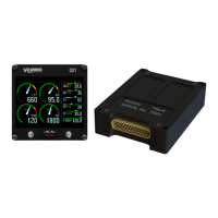
power and data lines interface with the TSLM via the 25-pin D-Sub connector on the side of the
unit.
Important Note:
After completing the TSLM system installation, verify it by performing the following tests before you
do the first engine start:
➔ Do a Diagnostic Test (Diagnostic Test and Troubleshooting, page 33)
➔ Do a RUN/MOTOR sequence (Run Operation, page 7)
Recommended wiring practices
NOTE: For all electrical connections, use correct splicing techniques, taking care to properly
insulate any exposed wire. A short circuit between any of the wires may cause damage to the
TSLM and/or other equipment.
VR Avionics does not supply connectors or wire for wiring up your TSLM. We recommend that
standard aircraft grade wiring and connectors be used during installation. 20 gauge wire is
sufficient for most lines to the unit. Make sure you protect the power lines with either a circuit
breaker or fuse sized appropriate to the wire you select. We recommend you use wire meeting Mil
Standard MIL-W-22759/16 (Tefzel insulation) which is available from various suppliers. Another
option is to use Teflon insulated wire which is available in various colors.
Connectors: We recommend you use machined pin connectors to mate with the TSLM connector.
Crimp connections have proven to be the most reliable in aircraft installations. D sub shells to hold
the pins are available from various sources. Purchasing quality connectors is a very wise
investment.
Installing: Make sure all connections are secure and all wires are routed and strain relieved to
ensure the wires will not chafe against any other object in the aircraft.
06/29/16 © 2016 VR Avionics page 14 of 33
 Loading...