TSLM - M601 Operational & Install Manual
Inter Turbine Temperature Sensing (ITT)
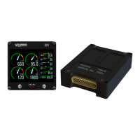
The figure below shows the hookup of the k-type thermocouple wires for ITT. At least within the
engine compartment thermocouple cable with metal braiding should be used. Note the ring
terminals where the one from the red wire is bigger than the other one.
Figure 15 - Inter-Turbine Temperature Sense Wiring
Sharing thermocouples with a temperature gauge is not a problem. Though thermocouples
provide a small signal (millivolts), this signal is strong (low source resistance). The TSLM's
thermocouple inputs have both high impedance and a wide common mode voltage range, which
ensure accurate but non-intrusive measurement.
Walter M601 type E-11 engines are equipped with 4 ITT wires, 2 for main instrumentation and 2
for an electronic limiting unit. For conformity we recommend connecting the red wire (ITT+) to pin 1
of the TSLM and the green wire (ITT-) to it's pin 14, when installing it on an type E-11 engine.
Beta Switch Sensing
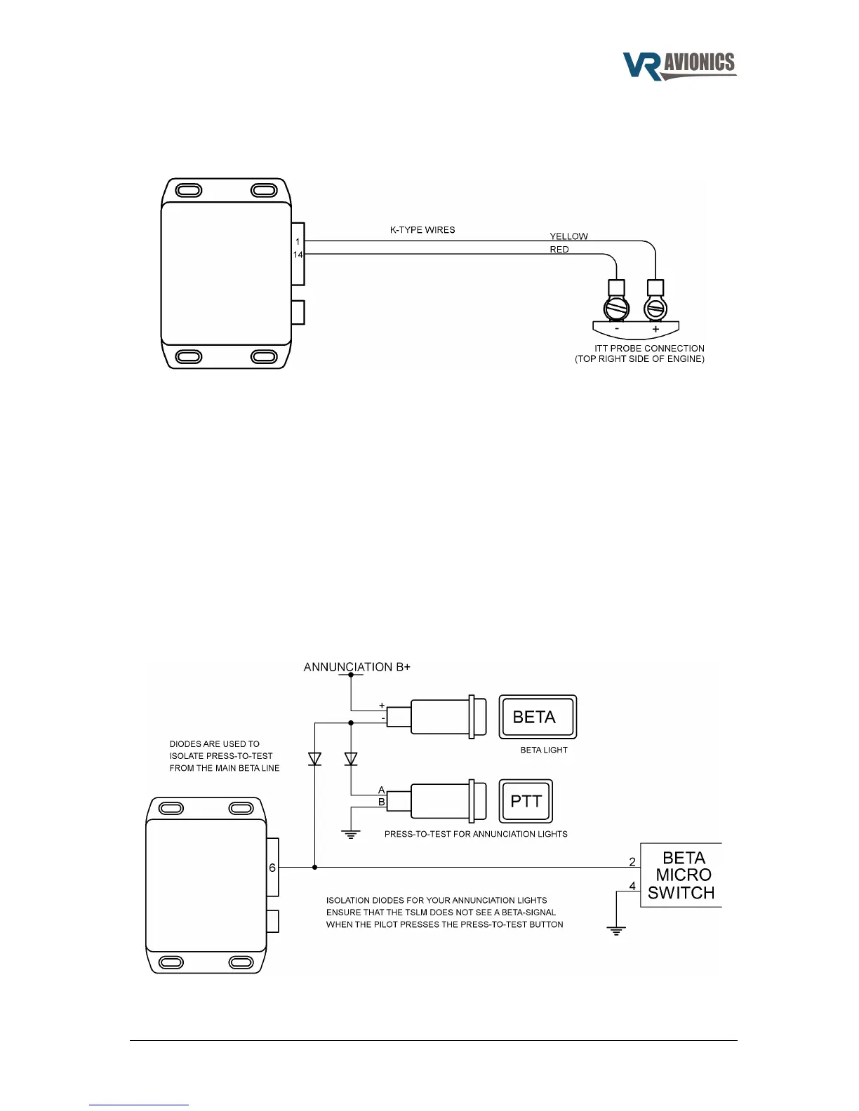
The TSLM has an auxiliary input (pin 6) that should be connected to the Beta switch wire. This wire
will be grounded when the propeller is in Beta and Reverse. The next diagram shows the practice
to follow when using a simple annunciation light system with a press-to-test feature. Employing the
diodes as shown below will prevent accidental beta propeller speed limiting when you push the
press-to-test button when using this basic annunciation system:
Figure 16 - Beta Sense Wiring
06/29/16 © 2016 VR Avionics page 22 of 33