TSLM - M601 Operational & Install Manual
Electrical installation of the TSLM system is divided in sections according to function. Sections
marked as ‘optional’ are not required for proper operation, but are recommended. The following
sections are the minimum requirement:
Power and Ground
Ignition Circuit
Start/Run Selection
Start Interrupter Valve
Start Contactor
Limiting (EHT) Circuit
TSLM Status Light
Exceed Light
Voltage Sensing
Gas Generator Speed Sensing (N1)
Propeller Speed Sensing (N2)
Inter Turbine Temperature Sensing (ITT)
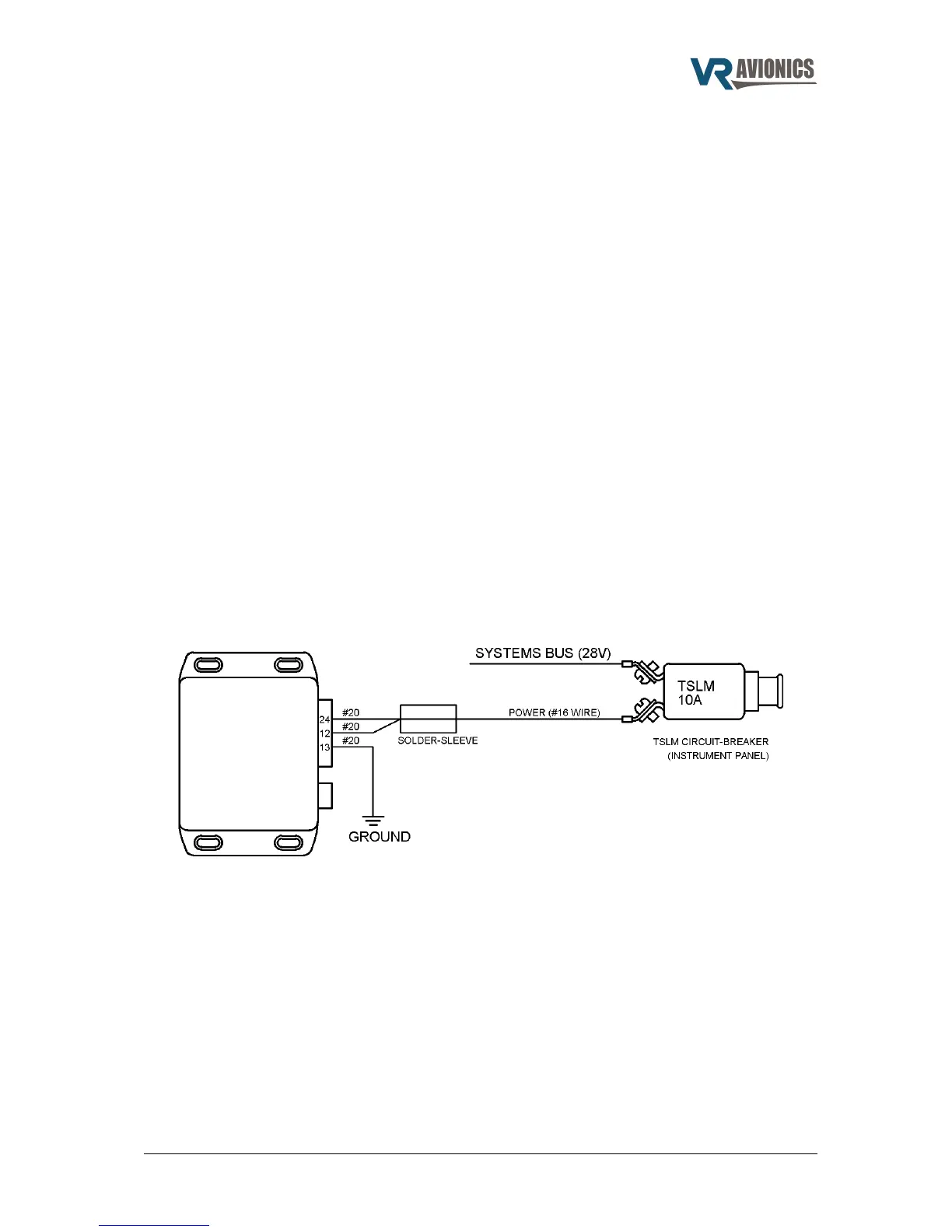
Power and Ground
The maximum current drawn by the TSLM unit is 10 Amps, thus we have to ensure the circuit-
breaker and the positive power wire will carry this current. This can be achieved by running one 16
AWG wire into one side of a solder-sleeve and two 20 AWG wires on the other side. The two 20
gauge wires then go to pins 12 and 24 of the TSLM module. The ground wire will not be carrying
large current, which means a single 20 AWG wire to pin 13 will be sufficient.
Figure 1 - Power and Ground Wiring
06/29/16 © 2016 VR Avionics page 15 of 33