5-54 BA E19 en* 1.0 * E19_10_510.fm
5 Operation
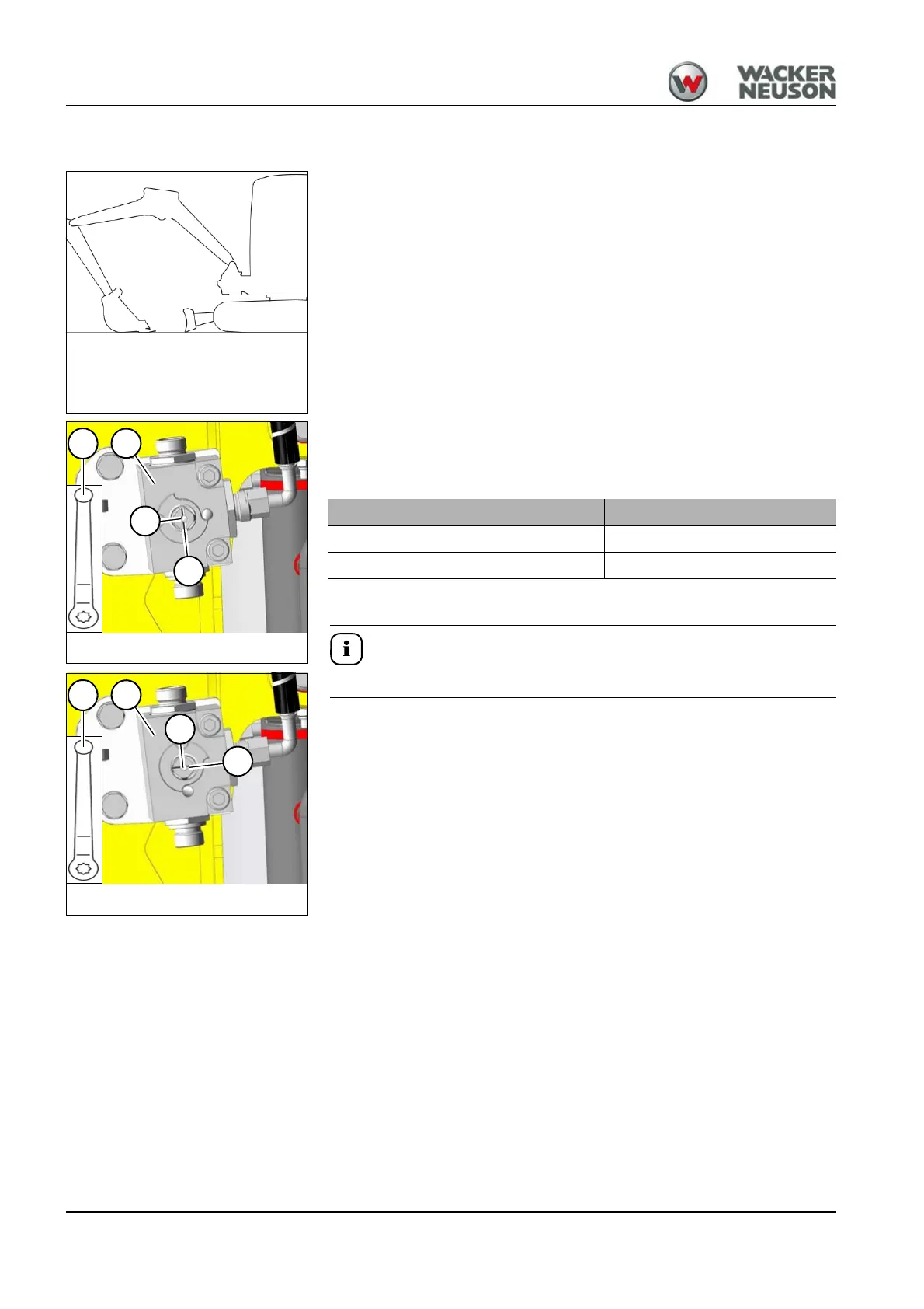
Control circuit of hydraulic thumb
The change-over takes place on the left and right at the end of the stick.
Position the arm system straight ahead at the center of the vehicle
(Fig. 215).
Lower the boom and the stabilizer blade to the ground.
Setting the hydraulic thumb:
Bring the ball-type cock A with lever B into the desired position to the left
and right on the stick.
The lever must be removed before operation.
The operation is executed using the right joystick – see chapter “ AUX I”
on page 5-29
Fig. 215 (Symbol representation)
Position of the slot C Operating
1 AUX I
2 Hydraulic thumb