BA E19 en* 1.0 * E19_10_510.fm 5-29
Operation 5
Additional control circuits
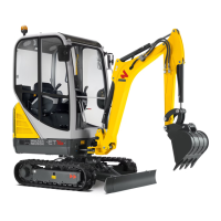
AUX I
The auxiliary hydraulics system is operated with the right control lever.
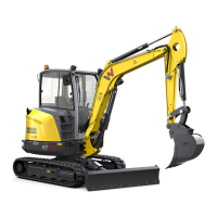
AUX II
Toggle between AUX II and AUX III with touch button A on the left
joystick.
The auxiliary hydraulics system is operated with the left control lever.
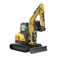
If the function AUX II is selected, the adjacent symbol for a few seconds in
the center of the display.
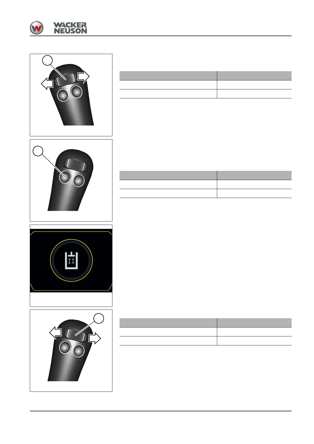
The auxiliary hydraulics system is operated with the left control lever.
Oil flow Position
To the line on the left Press switch B to the left
To the line on the right Press switch B to the right
Oil flow Position
To the line on the left Press switch B to the left
To the line on the right Press switch B to the right
Oil flow Position
To the line on the left Press switch B to the left
To the line on the right Press switch B to the right