wc_tx004431gb_FM10.fm
54
Operation LTV
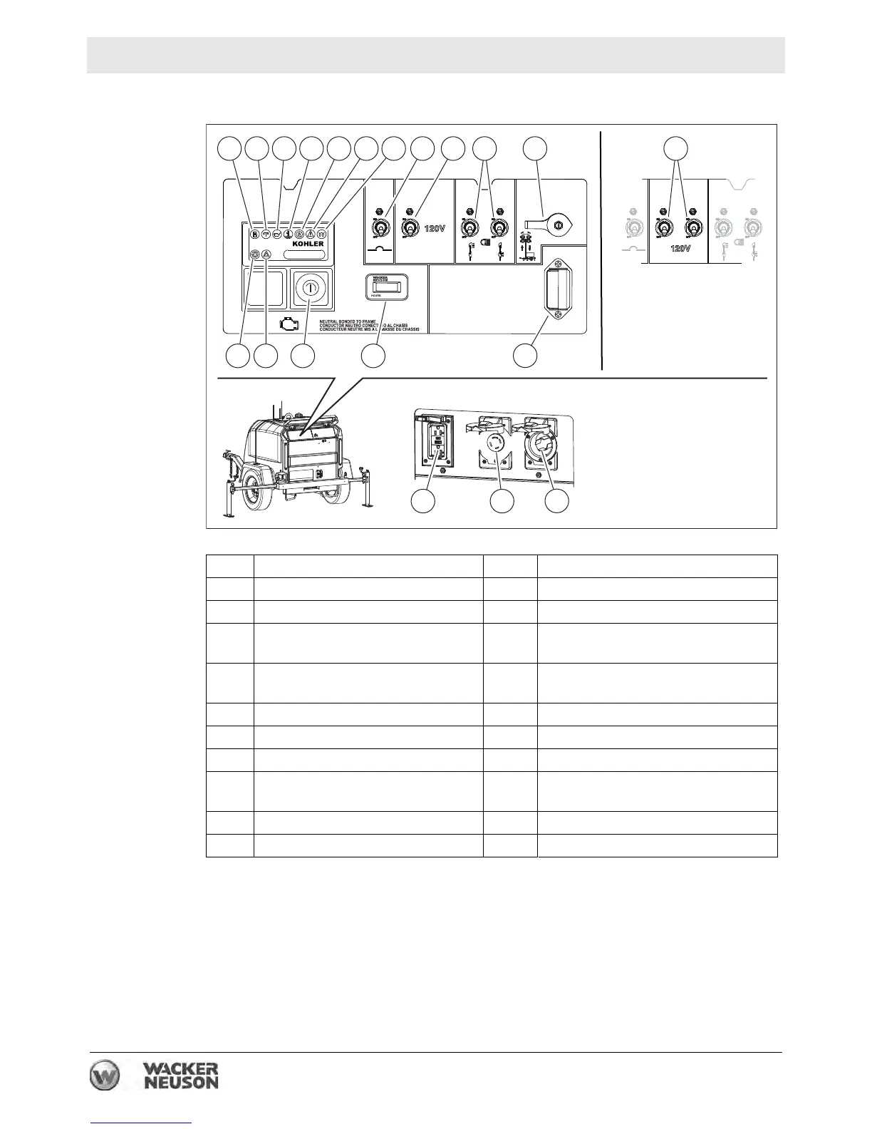
5.3 Control Panels and Receptacles—KOHLER
Ref. Description Ref. Description
a Low fuel indicator (not used) m Tower winch rotary switch (optional)
b Safety shut-down indicator n 20A GFI circuit breakers (optional)
c Low oil pressure shut-down
indicator
o Air filter restriction indicator
d High coolant temperature shut-
down indicator
p Auxiliary lights (not used)
e Alternator indicator q Key switch
f Auxiliary lights (not used) r Hour meter
g Glow plug indicator s Control panel light
h 50A main circuit breaker t 20A GFI receptacle
j 20A GFI circuit breaker u 30A receptacle (optional)
k 30A lights circuit breaker v Shore power inlet (optional)
wc_gr013750
h
g
f
e
dcba
j m
k
n
o
p q
r s
t
u
v