WM 90 Theory of Operation
wc_tx000388gb.fm 27
4.5 To Stop
See Graphic: wc_gr001454
4.5.1 Place throttle in the idle position (c2).
4.5.2 Turn engine switch to "OFF" (d).
4.5.3 Close fuel valve (e).
4.6 Component Descriptions
Component Illustration Component Description
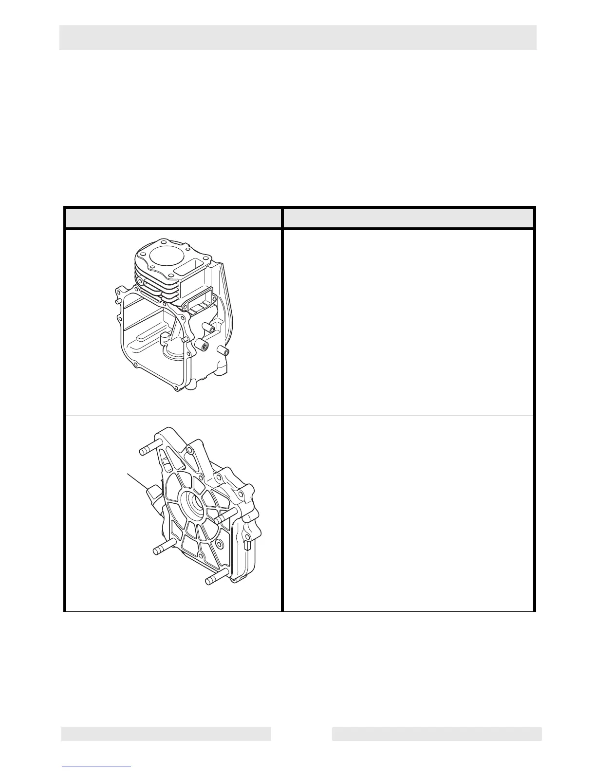
The cylinder/crankcase is a single piece alumi-
num die-casting. The cylinder liner, made of
special cast iron, is molded into the aluminum
casting. The crankcase has a mounting sur-
face on the output shaft side, where the main
bearing cover is attached.
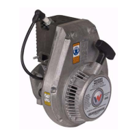
The main bearing cover is an aluminum die-
casting with thick reinforcing walls and ribs,
which is mounted on the output shaft side of
the crankcase. Remove the main bearing
cover to inspect the inside of the engine. Pilots
and bosses are machined on the cover for
direct mounting of the engine onto rammers.
Oil gauge (a).
wc_gr001870
wc_gr001871
a