WM 90 Theory of Operation
wc_tx000388gb.fm 29
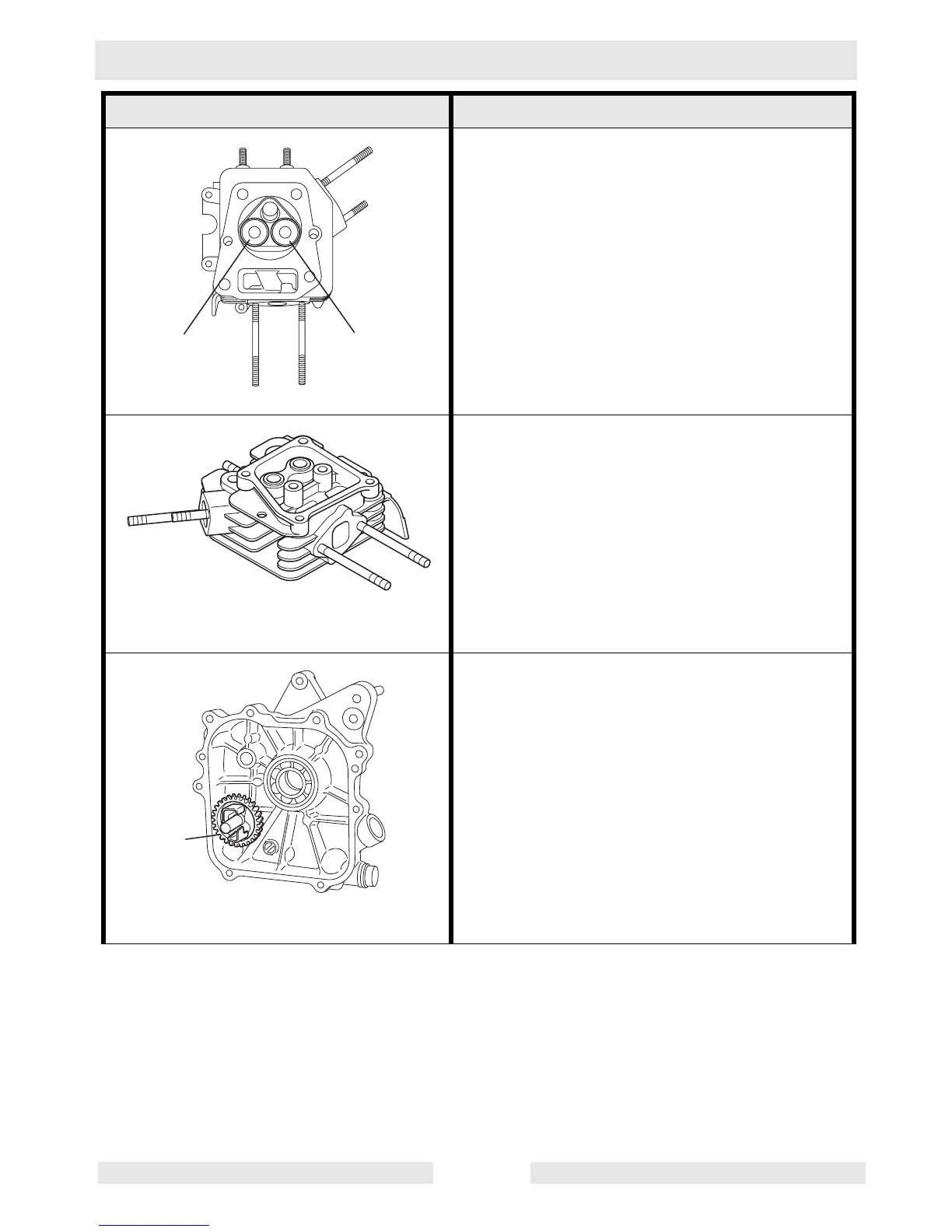
The intake valve is located on the flywheel side
of the cylinder head. Hard alloy valve seats are
molded in the cylinder head and satellite is
fused to the exhaust valve face. The cylinder
baffle leads cooling air to the exhaust valve
area for optimum cooling.
Reference: intake (a); exhaust (b).
The cylinder head is an aluminum die-casting
which utilizes wedge-type combustion cham-
ber for high combustion efficiency.
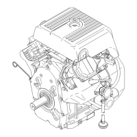
The governor is a centrifugal flyweight type
which ensures constant operation at the
selected speed during load variations. The
governor gear (a) with governor weights is
installed on the main bearing cover.
Component Illustration Component Description
wc_gr001876
IN
EX
ab
wc_gr001877
wc_gr001878
a