15
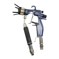
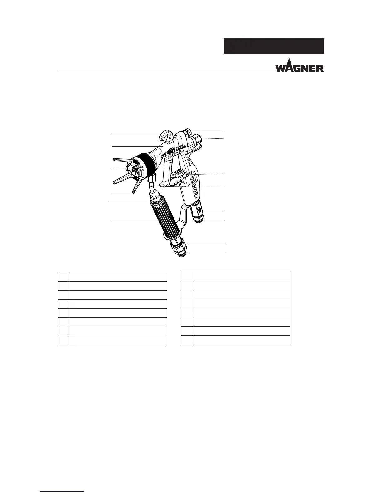
AC 4600 Pro
B_02697
A
H
I
J
K
L
B
C
D
E
F
G
M
N
OPERATING MANUAL
EDITION 02/2009
PART NO. DOC394871
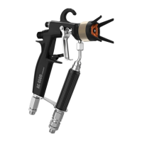
Description
A Suspension hook
B Shaping air regulator
C Spring cover
D Trigger guard
E Trigger safety
F Air connection
G Paint connection
4.4.2 FUNCTIONS OF THE GUN
Pulling the trigger (D) approximately 1/2 way opens the air valve allowing atomising and
shaping-air to fl ow through the aircap (I). When the trigger is pulled further, more resist-
ance is felt and the material valve is opened. The atomising air control (B) adjusts the total
quantity of air fl owing trough the spray gun.
The spray gun is rendered safe with the trigger safety catch (E). (Turn the trigger safety
catch in the spraying direction and fasten in the groove).
4.4 FUNCTIONAL DESCRIPTION
4.4.1 DESIGN OF SPRAY GUN
Description
H Union nut with nozzle guard
I Nozzle / Air cap
J Gun housing
K Filter housing
L Handle tube
M Swivel Air
N Swivel Material
 Loading...