19
B_04101
1
3
4
7
7
6
10
11
12
5
9
14
8
2
13
OPERATING MANUAL
VERSION 11/2015 ORDER NUMBER DOC2333553
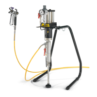
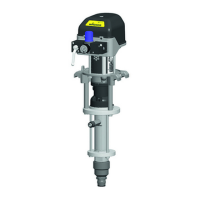
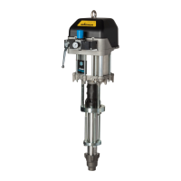
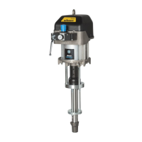
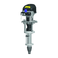
5 DESCRIPTION
5.1 COMPONENTS
1 Air motor
2 Air inlet
3 Mounting ange
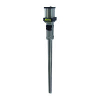
4 Separating uid tank
5 Product outlet
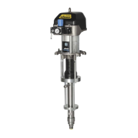
6 Fluid section
7 Product inlet
8 Grounding connection
9 Reversing valve
10 Safety valve (air motor vent)
11 Air pressure regulator
12 Ball valve
13 Air outlet to the reversing
valve
14 Air inlet to the reversing
valve
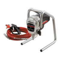
The piston pump is driven with compressed air (2). This compressed air moves the air
piston up and down in the air motor (1) and it also moves the the associated pump piston
up and down in the uid section (6). At the end of each stroke, the compressed air ow is
redirected by a reversing valve (9).
The working material is sucked up during the upwards stroke and is continuously conveyed
towards the product outlet (5) in both stroke directions.
Air motor (1)
The air motor with its pneumatic reverse (9) does not require pneumatic oil.
The compressed air is fed to the motor via an air regulator (11) and the ball valve (12).
Fluid section (6)
The uid section has been designed as a piston pump with exchangeable ball valves. The
pump piston runs in two xed packings which are self-adjusting by means of a pressure
spring, thus resulting in a long service life.
Between the air motor and the uid section there is a separating agent cup (4) for holding
the separating agent.
5.2 MODE OF OPERATION
 Loading...