40
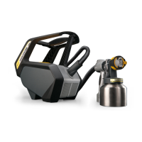
Super Finish 33 PLUS/PRO • Nespray Pro
FUNCTIONAL TEST WORK INSTRUCTION
2.1 FUNCTIONAL TEST OF CORD SET
1. Ensure safe isolation from the supply before commencing work.
2. A multimeter or test buzzer should be used for testing. The function should be checked rst of all.
3. Attach a measuring lead to one of the two pins on the connector.
4. Attach the second measuring lead to one of the device terminals N (blue) or L1 (brown). If no tone is audible or if the mea-
suring device indicates an in nitely high resistance, the measuring lead must be attached to the other terminal, as it is not
possible to tell to which pin the respective wire is connected on the earthing pin plug. If a tone is now audible or if the mea-
suring device actuates, this wire is ok. Move the connecting cable in order to rule out a defective contact; if no interruption
is discernible, this wire is ok. Repeat with the other wire N (blue) or L1 (brown).
5. Repeat point four in order to verify the functionality of the protective conductor (green/yellow). This is only necessary for
equipment class I. See chapter 4.3
6. If an interruption or defective contact is found in one of the wires, then the wire is defective.
7. The defective component must be made inoperative in order to prevent further use.
2.2 FUNCTIONAL TEST OF THE CAPACITOR
1. Ensure safe isolation from the supply before commencing work.
2. An insulation resistance tester (e.g. Metriso 500) must be used for the measurement.
3. The capacitor must be electrically isolated from the device. To do this, disconnect the plug connector on the capacitor.
4. Set the measuring device (Metriso 500) to measuring range III.
5. Connect the two test probes of the measuring device to the two terminal lugs on the capacitor.
6. To start the measurement, press the test button on the handle.
7. The measuring device de ects fully, then after approx. 20 sec. the pointer begins to wander to the left. The measurement is
only complete when the pointer has moved all the way to the left (zero de ection).
8. Now disconnect the measuring device from the capacitor and switch to the Volt (V=) position.
9. After approx. two minutes, reconnect the test probes to the capacitor (point 5). The display begins to wander from right
(full de ection) to left (zero de ection).
10. If a deviation is found at point seven, for instance if the pointer remains at full de ection (right) or zero de ection (left) for
more than a minute, then this capacitor is defective.
11. The defective component must be made inoperative in order to prevent further use.
GB

 Loading...