Assembly Instructions
21
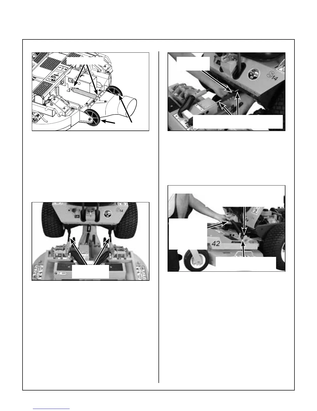
Attach Spring
Roller Wheels
Tilt-Up Spring and Roller Wheel
Installation on Rear Discharge Deck
Mower Deck Installation on Tractor
Deck Installation
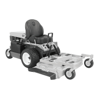
1. Lightly grease each deck support arm (2) on the
tractor. Refer to Mower Deck Installation
photo for location of deck support arm.
Deck Support
Arms
Mower Deck Installation
2. Engage the deck carrier frame tube sockets on
the tractor support arms (refer to Discharge
Chute and PTO Shaft Guard Installation pho-
to for socket location). Slide the deck onto the
support arms approximately 3 in. (76 mm).
3. Align and connect the splined PTO shaft and
socket halves, as shown in PTO Shaft Connec-
tion photo. The PTO shaft has a pilot end to
ease alignment of shaft; t shaft end into socket
and rotate shaft until the splines line up as indi-
cated by arrows, then slide together.
Arrows on Shaft and Tube
(Used to Align When Sliding Together)
PTO
Connection
PTO Shaft Connection
4. Install the hitch pin through the hole on the end
of each support arm to lock the deck in place
(refer to Deck Counterweight Spring Installa-
tion photo). Two (2) hitch pins are included in
the Owner’s Packet of materials.
Hitch Pins Lock Deck
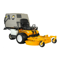
on Support Arms
Counterweight
Springs Clip
Onto Body
With Forward
Body Tilted Up
Spring Tension Adjustment Nut
Located Under Lower
Spring Hook (Not Visible)
Deck Counterweight Spring Installation
5. Raise mower body (instead of lifting the front of
deck) and clip the counterweight springs to the
receptacle on front of body. Lower the body to
tension the springs. (Refer to Deck Counter-
weight Spring Installation photo.)
6. With the counterweight springs connected, the
weight on the deck caster wheels should be
15 to 25 Ib (6.8 to 11.3 kg); this adjustment is
preset at the factory. If required, the spring ten-
sion can be adjusted by tightening or loosening
the elastic stop nuts located underneath the
lower spring hook, or contact your local dealer
if additional help is required. Refer to Deck
Counterweight Spring Installation photo.