66
Maintenance Instructions REPLACING/REPAIRING
Blade Overload Shear Bolts
NOTE: Blade shear bolts are not used on belt driv-
en decks.
On gear driven decks each cutting blade is keyed to
a blade hub by two (2) shear bolts (10-24 x 5/8 in.
stainless steel machine screws). These bolts are
designed to shear and protect the blade drive gear-
box from damage if the blade encounters a shock
load.
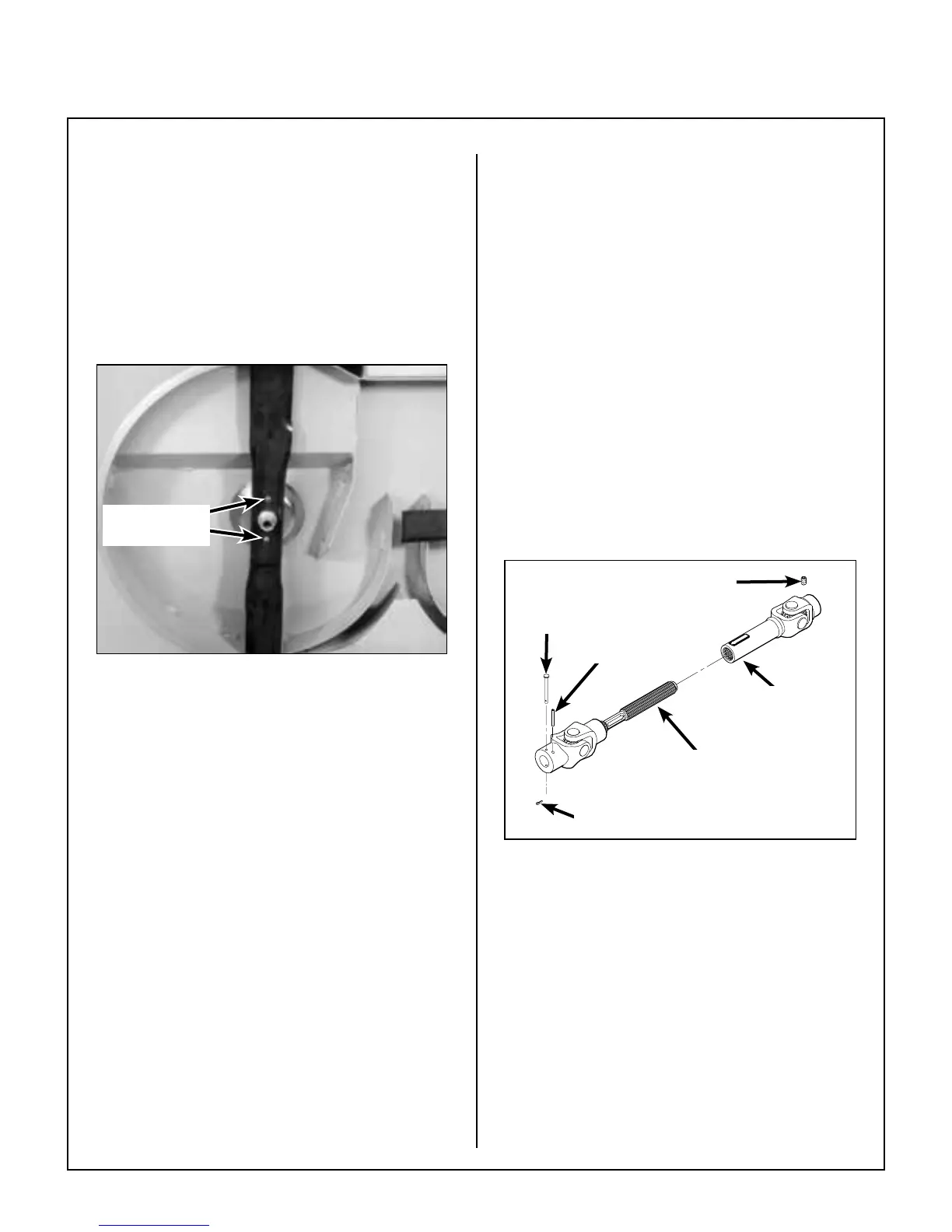
Cutting Blade
Shear Bolts
Cutting Blade Shear Bolts
NOTE: Tightening the 5/8-18 blade mounting nut
to 60 lb·ft (81 N·m) is also important for proper
shock load protection. It is important to not over-
tighten the mounting nut since this defeats (over-
rides) the function of the shear bolts.
If these bolts shear, remove the blade and install
new bolts. Refer to CHECKING/SERVICING in
this section for Sharpen Mower Blades which de-
scribes the blade removal and installation proce-
dure.
After reinstalling the blade, check blade timing (on
gear driven decks) by moving blades through one
(1) complete revolution. Make sure blade tips
pass clear of each other. If timing is incorrect, con-
tact your Walker dealer.
PTO Shear Pin (If Equipped)
The PTO drive shaft connection to the deck gearbox
has a shear pin to provide shock load protection to
the mower deck drive. This system provides pri-
mary shock protection in case of blade impact and
will normally shear before the individual shear bolts
on the blade hub.
When the PTO pin has sheared, use the following
procedure to replace it:
1. Loosen the two bolts securing the PTO shaft
guard on the deck; lift the guard off. (Holes in
guard are slotted for easy removal.)
2. Rotate U-joint on shaft to align the shear pin
hole with the hole (and shear pin fragment) in
the shaft. Use a punch to drive the remaining
portion of the old shear pin out.
3. Install new shear pin and secure with cotter pin.
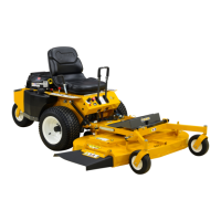
U-Joint
Shaft Assembly
U-Joint
Tube Assembly
Cotter Pin
Shear Pin
Set Screw
Split Spring Pin
PTO Shear Pin
IMPORTANT: Use only Walker P/N 8067-13
shear pins for replacement to provide proper
shock protection -- these pins are hardened to
shear under a specic amount of load.
4. Reinstall the PTO shaft guard.
Before operating the deck, inspect the blade over-
load shear bolts and also check blade timing (on
gear driven decks) by moving blades through one
(1) complete revolution. Make sure blade tips
pass clear of each other. If timing is incorrect, con-
tact your Walker dealer.