73
Maintenance Instructions ADJUSTMENTS
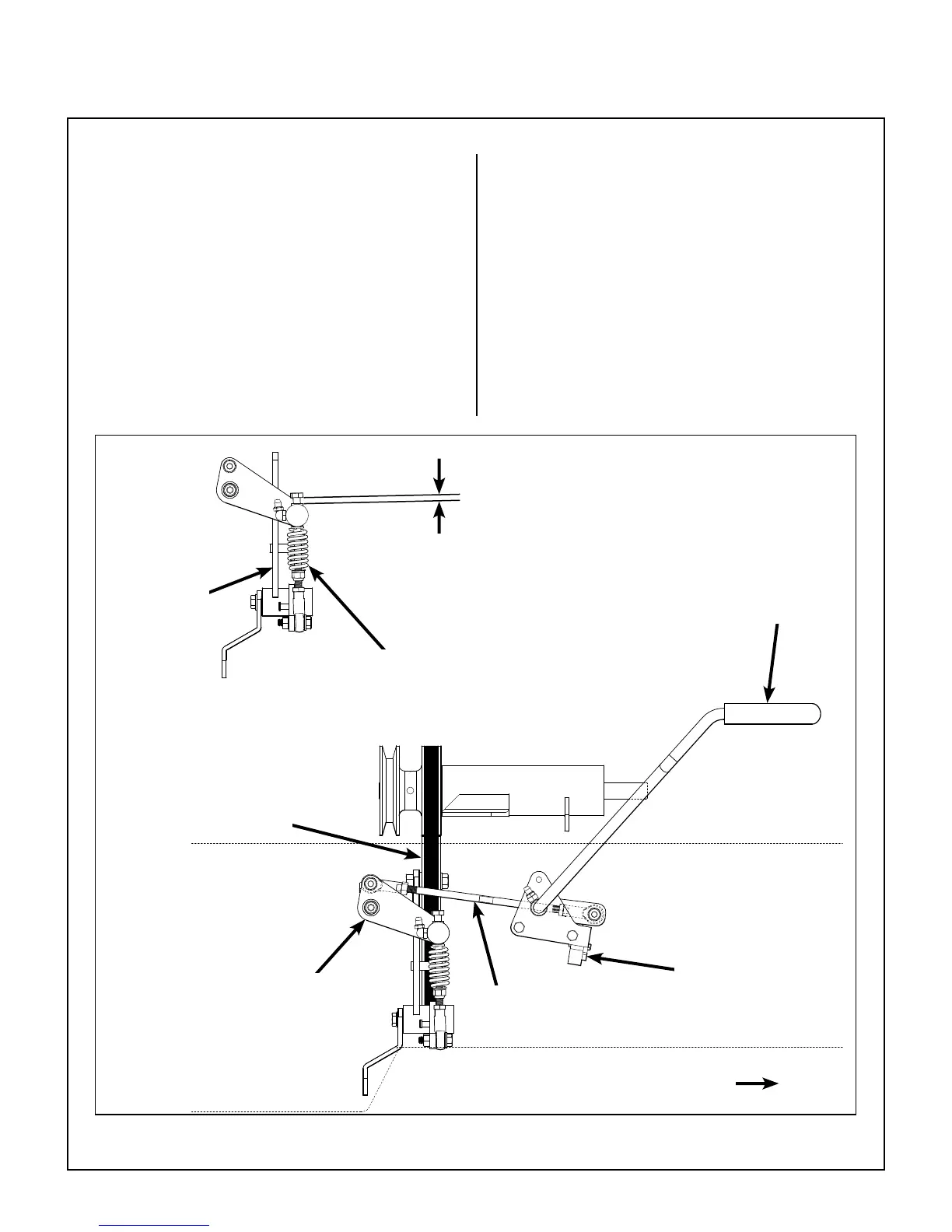
Blade Clutch (PTO)
Clutch Engagement/Belt Tension
The clutch engagement and PTO belt tension are
adjusted using the clutch actuator rod. After install-
ing a new PTO belt, after 10 hours and every 100
hours thereafter, check and adjust for the clutch
spring assembly bolt head clearance dimension as
shown in the PTO Clutch Engaged illustration. If
the clutch actuator rod or clutch spring assembly
have been disassembled, rst reset them to their
factory preset lengths (see PTO Clutch Disen-
gaged illustration) and then proceed with adjust-
ment as follows.
With the clutch engaged, adjust the length of the
clutch actuator rod to achieve a clutch spring
assembly bolt head clearance of 1/4 in. to 5/16 in.
(6.5 mm to 8 mm). To adjust the clutch actuator rod
length, loosen both ball joint jam nuts (one ball joint
will have LH threads) and shorten the rod to
increase the clutch spring assembly bolt head
clearance, or lengthen the rod to decrease the bolt
head clearance. If adjustments are needed more
frequently than every 100 hours to maintain
dimensions, it may suggest problems with pulley
wear or belt misalignment.
PTO Clutch Engaged
Blade Clutch
Engaged
Bolt Head Clearance
1/4 in. to 5/16 in.
(6.5 mm to 8 mm)
Clutch
Actuator Arm
Clutch Spring Assembly
(Spring Compressed)
Clutch Idler
Arm
Front of Mower
Blade Clutch
Idler Pulley
Safety
Switch
Clutch
Actuator Rod