5.0 INSTALLATION AND FIXING
VL
2
VAL.130.--.M.EN Issue: A1
09.16
28
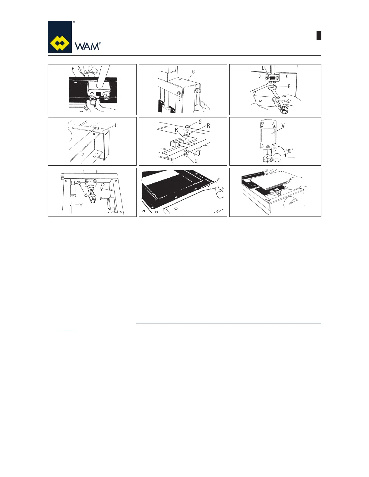
5) Place the M12 bolts and the large washers on top side of the blade (F). Insert the small washers and self-
locking nuts without tightening completely.
6)7LJKWHQWKHEROWVWKDW¿[XSSHUFURVVSLHFHG) to valve frame.
7)/RRVHQE\DTXDUWHUWXUQWKHEXVK¿[LQJQXWVD) and (E). Tighten the bottom nut (E) to the top one (D).
8),IUHTXLUHGQRZ¿WWKHVROHQRLGYDOYHIRUSQHXPDWLFDFWXDWRUWRWKHVXSSRUWEUDFNHW+VXSSOLHGVHSDUDWHO\
by using 2 crosspiece connecting bolts.
9) Position the washers Ø 12 (RRQWKHERWWRPVLGHRIWKHEODGHOQVHUWWKHURXQGKHDGEROW0[6DQG¿[
from the top side using washers Ø 8 (T) and nuts (U).
10) Position the arms of limit switches (VWRVRWKDWDIWHUKDYLQJ¿WWHGWKHUROOHUVWKH\IDFHWKHEODGHVORWV
11) Fix the Iimit switches on the inside using nuts and bolts. Open the valve to 0 position, the head of the bolt
(S) must rest on the limit switch roller. The bores (Y) are cable passages. Check the switch operation be-
fore starting regular operation. 5HIHUWRVSHFL¿FSURFHGXUHIRUOLPLWVZLWFKDVVHPEO\UHSRUWHGLQWKHQH[W
section.
12) For valve installation use bolts which are short enough not to interfere with blade.
13):KHQDVVHPEO\LVFRPSOHWH¿WWKHWRSDQGERWWRPJXDUGHQVXULQJWKH\SHUIHFWO\DGKHUHWRWKHIUDPHDQG
check the positioning of the self-adhesive gasket.
56 7
89 10
11
12
13