5.0 INSTALLATION AND FIXING
VL
2
VAL.130.--.M.EN Issue: A1
09.16
29
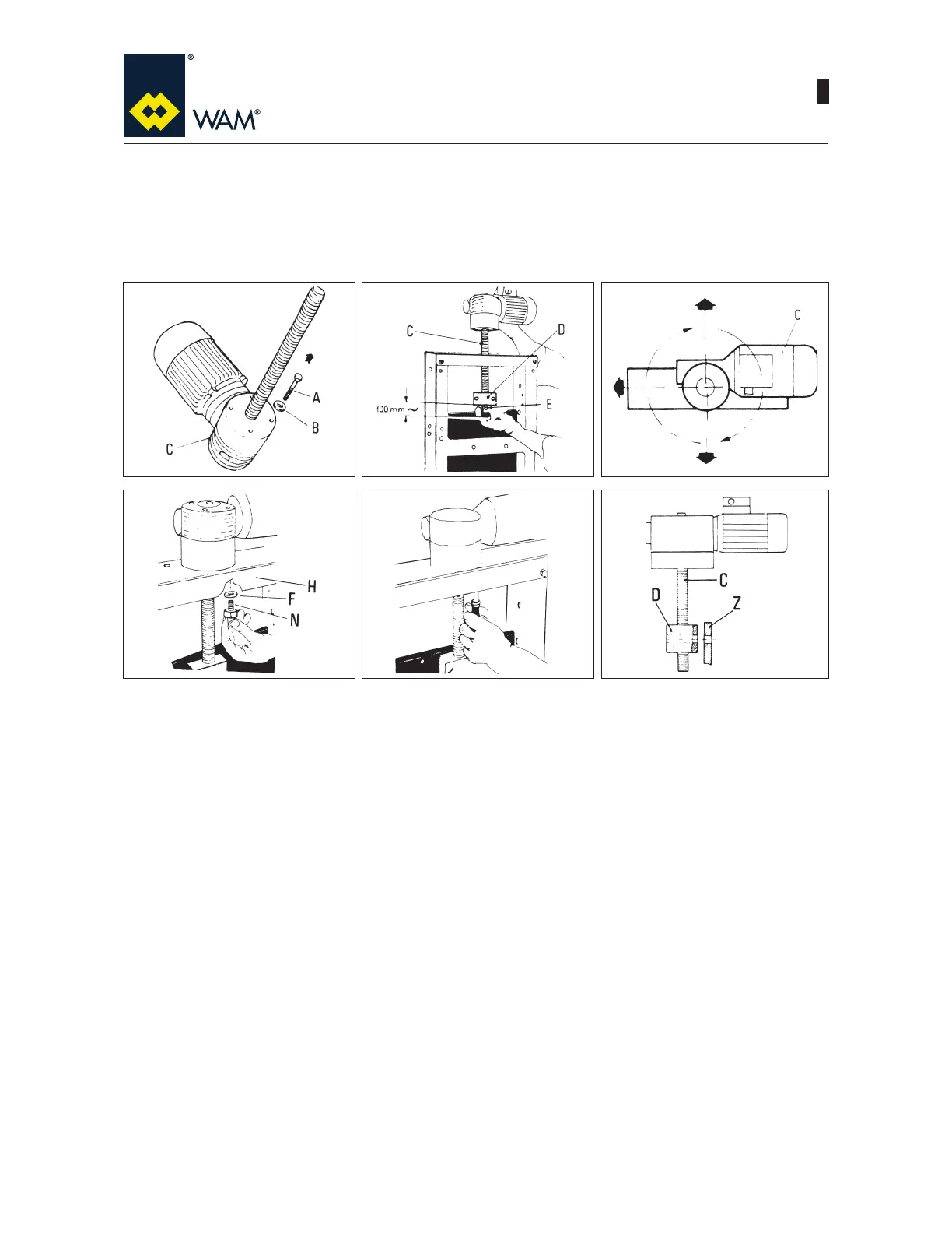
SUPPLY:
C) 1 gear motor actuator
D) 1 nut screw
V) 2 solenoid valves
%ROWVQXWVDQGZDVKHUV
&DUGERDUGER[
NOTE: During installation the blade has to be supported on all bearings. Only after having checked this, up-
end valve for actuator assembly.
1) Remove the 4 bolts (A) and washers (B) from the actuator.
2) Insert the actuator spindle (C) in the central bore on the upper crosspiece of the valve body. Screw the nut
screw (D) on the spindle by approx. 100 mm with the greasing nipple (E) pointing outside.
3) Choose the position of actuator (C).
4) Insert the 4 washers (F) and bolts (N) from below through the upper crosspiece (H) in threaded bores of the
actuator.
5) Tighten the bolts.
6) Turn the spindle (C) by hand until the bores on nut screw (D) and those on blade (Z) match.
1
23
456