5.0 INSTALLATION AND FIXING
VL
2
VAL.130.--.M.EN Issue: A1
09.16
30
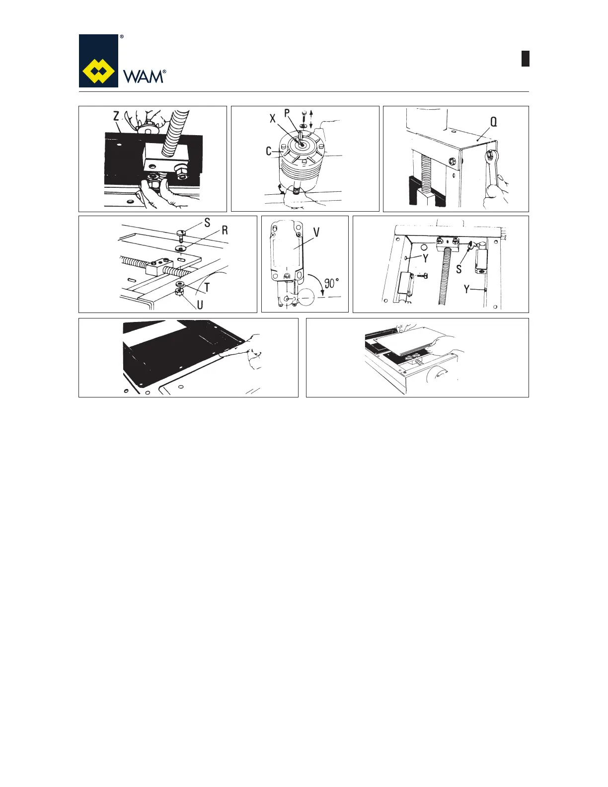
7) Insert from above into the blade (Z) the two M12 bolts along with the large washers. Insert the small washers
and screw on the self-locking nuts from below without tightening them up.
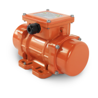
8) Remove the central bolt and washer from the actuator top side. Turn the spindle by hand until the key slots in
the reducer housing (X) are aligned. Insert the parallel key (PDQGUH¿WWKHFHQWUDOEROWDQGZDVKHU7LJKWHQ
the bolt.
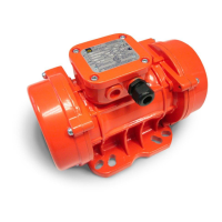
9)7LJKWHQWKHEROWVWKDW¿[WKHXSSHUFURVVSLHFHQ) to valve frame.
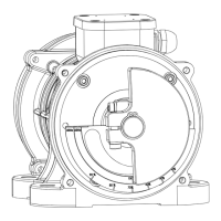
10) Position the washers D.12 (R) on the rear side in the centre of the slots. lnsert the round head screws
M8x25 (S). Insert the washers D.8 (T) and nuts (U) from the opposite side.
11) Position arms of limit switches (VWRVRWKDWDIWHUEHLQJ¿WWHGWKHUROOHUVIDFHWKHEODGHVORWV
12) Fix the Iimit switches to the inside using nuts and bolts. Open the valve on 0 position, the head of the bolt
(S) must rest on limit switch roller. Bores (Y) are cable passages. Check the switch operation before start-
LQJUHJXODURSHUDWLRQ5HIHUWRVSHFL¿FSURFHGXUHIRUOLPLWVZLWFKDVVHPEO\UHSRUWHGLQWKHQH[WVHFWLRQ
13) For valve installation use bolts which are short enough not to interfere with blade.
14) Carry out greasing (see Lubrication chapter).
15) Fit the top and bottom guard ensuring they perfectly adhere to the frame. Check the positioning of the self-
adhesive gasket.
789
10
11
12
13 14