EasyManua.ls Logo

Warmup 3IE - SETTING YOUR PROGRAM (Contd); Pre-set Room Schedules

Warmup 3IE
28 pages
Print Icon
To Next Page IconTo Next Page
To Previous Page IconTo Previous Page
Loading...
24/7 Technical hotline - Ligne d’assistance technique - Línea de asistencia técnica
US 1.888.927.6333 / CA 1.888.592.7687
7
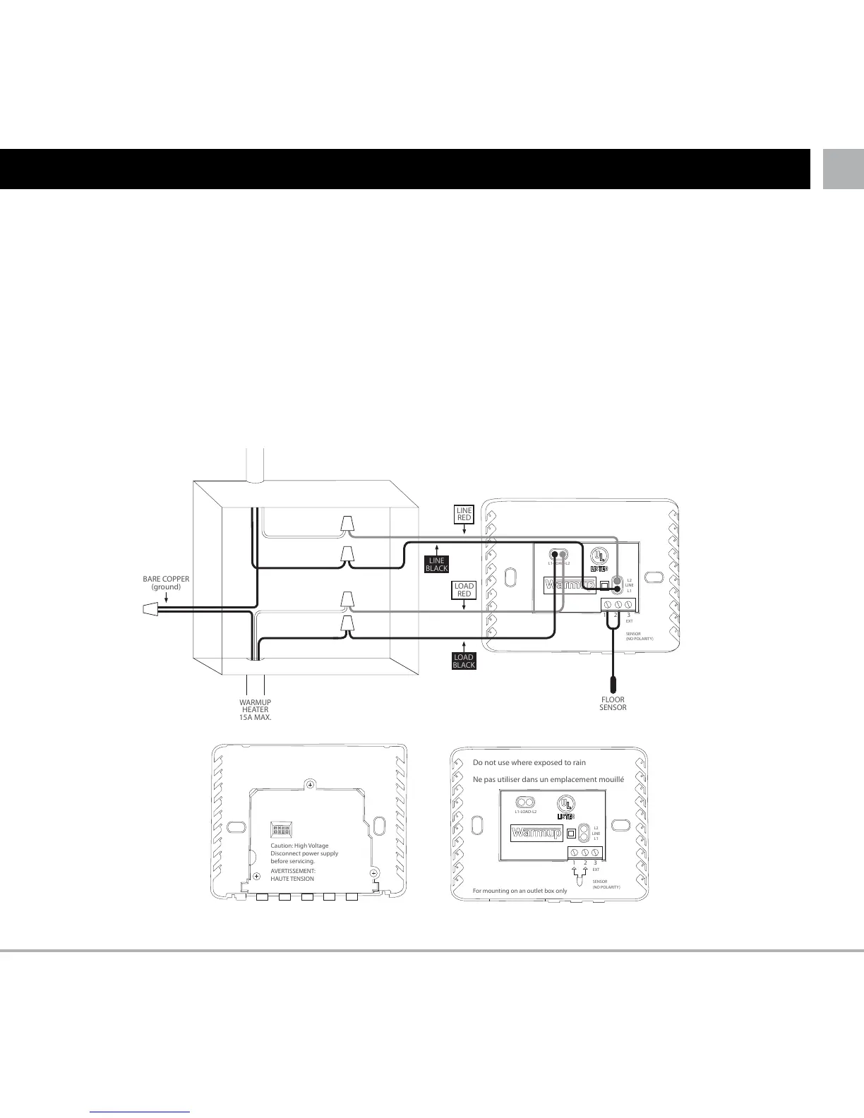
Connect the power base wires to the power supply and load using twist-on wire connectors for copper
wires (see diagram below), as supplied in the packaging box.
• ConnectthepowerlinetothethermostatlinecablesmarkedL1andL2.
• ConnecttheheatingcabletothethermostatloadcablesmarkedLoad1andLoad2.(max15amps)
• Connectto1stwireoffloorsensortoterminal1(colournotimportant)
• Connectto2ndwireoffloorsensortoterminal2(colournotimportant)
NOTE: All cables and connections must be carried out by a qualified electrician and must conform to
the local electrical code.
ELECTRICAL WIRING
Caution: High Voltage
Disconnect power supply
before servicing.
AVERTISSEMENT:
HAUTE TENSION
For mounting on an outlet box only
1
2
3
EXT
SENSOR
(NO POLARITY)
L1-LOAD-L2
L2
LINE
L1
Ne pas utiliser dans un emplacement mouillé
1
2
3
EXT
SENSOR
(NO POLARITY)
L1-LOAD-L2
L2
LINE
L1
LOAD
RED
LOAD
BLACK
LINE
BLACK
LINE
RED
BARE COPPER
(ground)
FLOOR
SENSOR
WARMUP
HEATER
15A MAX.

Other manuals for Warmup 3IE

Related product manuals