4
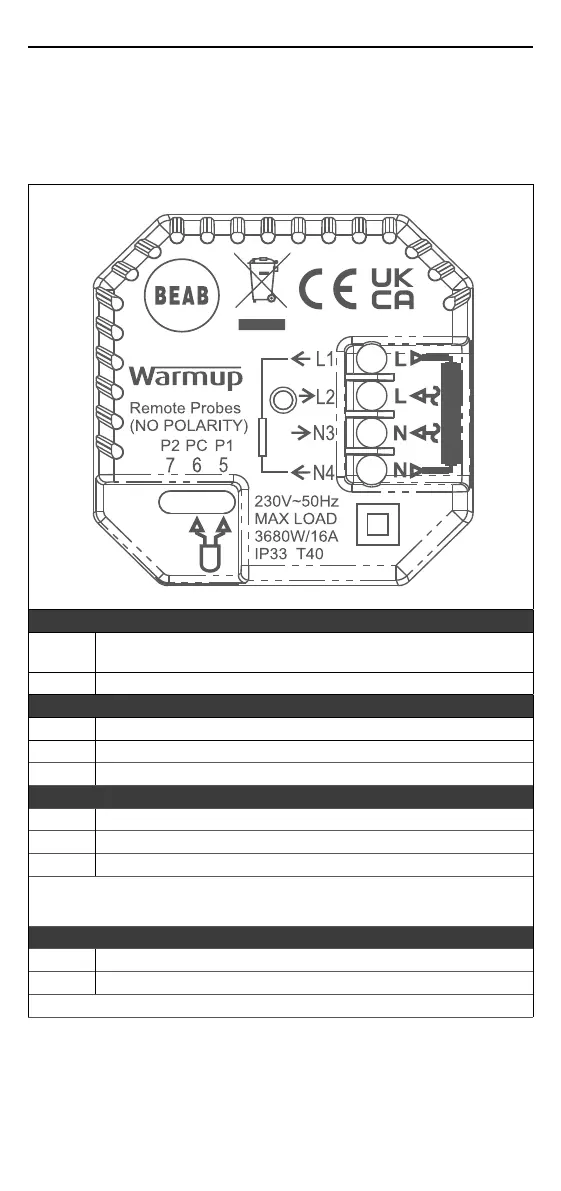
Step 2 - Wiring Connections
WARNING!
The thermostat must be installed by a qualied electrician in accordance with
the current edition of the BS7671 Wiring Regulations.
NOTE: For loads above 10 A, the conductor wire gauge should be at least
2.5mm²
Electric Underoor Heating
L1 & N4
Heater Live and Neutral
Max. 16A (3680W)
L2 & N3 Supply Live and Neutral
Hydronic Underoor Heating
L1 Switched Live to Wiring Centre
L2 & N3 Supply Live and Neutral
N4 Not Used
Central Heating
L1 Switched Live to Zone Valve /Boiler
L2 & N3 Supply Live and Neutral
N4 Not Used
For extra low voltage or volt-free systems a contactor must be used.
Connecting the thermostat directly to extra low voltage or volt-free boilers
may cause damage to the boiler circuit.
Sensor Connection
5 & 6 Probe 1 - Floor/Air Control Sensor (No Polarity)
6 & 7 Probe 2 - Limit Sensor (No Polarity)
See Table 1.0 for thermostat use cases