Flow meter, booster unit (1I01)
If a fuel consumption meter is required, it should be fitted between the feed pumps and the
de-aeration tank. When it is desired to monitor the fuel consumption of individual engines in
a multiple engine installation, two flow meters per engine are to be installed: one in the feed
line and one in the return line of each engine.
There should be a by-pass line around the consumption meter, which opens automatically in
case of excessive pressure drop.
If the consumption meter is provided with a prefilter, an alarm for high pressure difference
across the filter is recommended.
De-aeration tank, booster unit (1T08)
It shall be equipped with a low level alarm switch and a vent valve. The vent pipe should, if
possible, be led downwards, e.g. to the overflow tank. The tank must be insulated and equipped
with a heating coil. The volume of the tank should be at least 100 l.
Circulation pump, booster unit (1P06)
The purpose of this pump is to circulate the fuel in the system and to maintain the required
pressure at the high pressure pumps, which is stated in the chapter Technical data. By
circulating the fuel in the system it also maintains correct viscosity, and keeps the piping and
the high pressure pumps at operating temperature.
Heater, booster unit (1E02)
The heater must be able to maintain a fuel viscosity of 14 cSt at maximum fuel consumption,
with fuel of the specified grade and a given day tank temperature (required viscosity at high
pressure pumps stated in Technical data). When operating on high viscosity fuels, the fuel
temperature at the engine inlet may not exceed 135°C however.
The power of the heater is to be controlled by a viscosimeter. The set-point of the viscosimeter
shall be somewhat lower than the required viscosity at the high pressure pumps to compensate
for heat losses in the pipes. A thermostat should be fitted as a backup to the viscosity control.
To avoid cracking of the fuel the surface temperature in the heater must not be too high. The
heat transfer rate in relation to the surface area must not exceed 1.5 W/cm
2
.
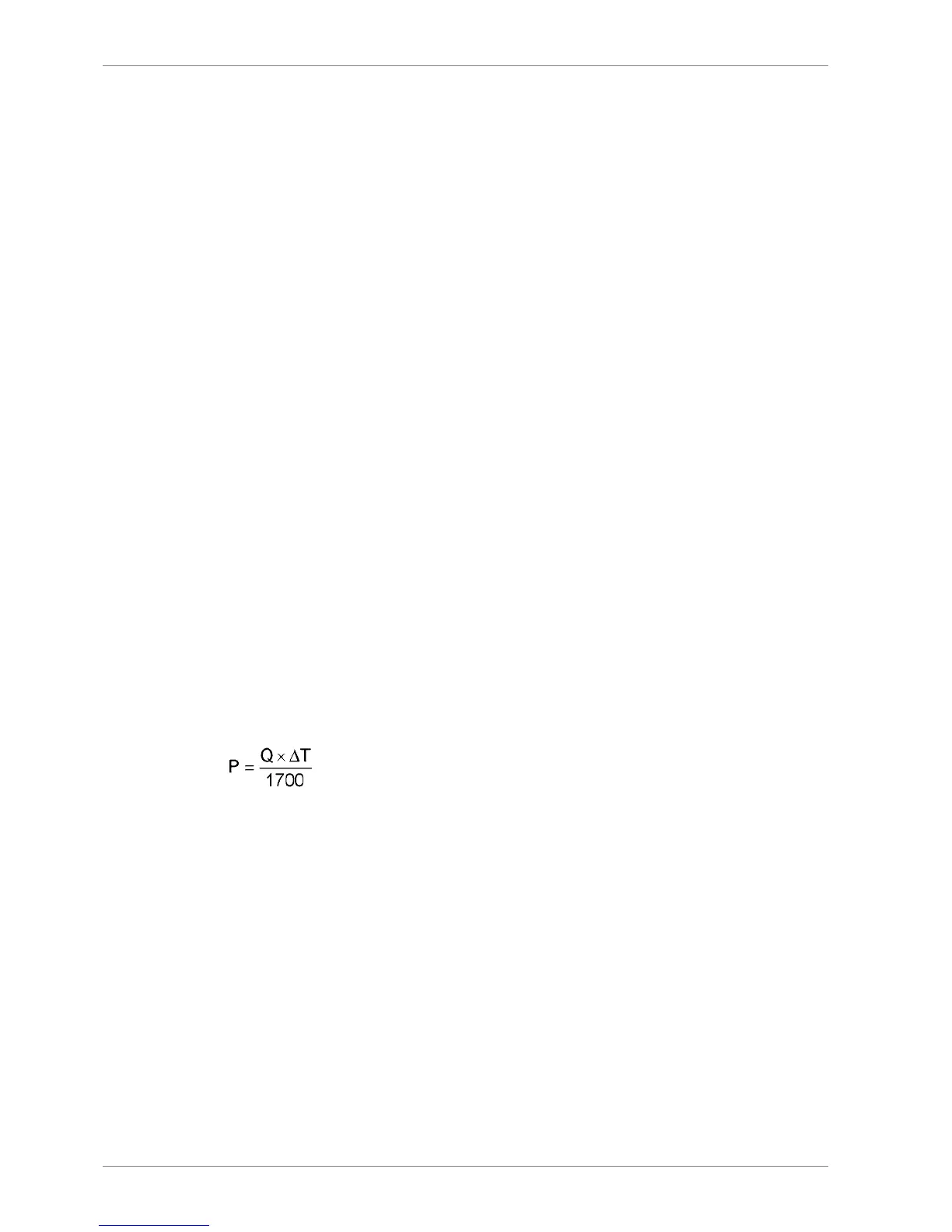
The required heater capacity can be estimated with the following formula:
where:
heater capacity (kW)P =
total fuel consumption at full output + 15% margin [l/h]Q =
temperature rise in heater [°C]ΔT =
Viscosimeter, booster unit (1I02)
The heater is to be controlled by a viscosimeter. The viscosimeter should be of a design that
can withstand the pressure peaks caused by the high pressure pumps of the diesel engine.
Design data:
0...50 cStOperating range
180°CDesign temperature
4 MPa (40 bar)Design pressure
6-36 DBAE248994
Wärtsilä 31DF Product Guide6. Fuel Oil System
 Loading...


