23833A141
IMPORTANT SAFETY INSTRUCTIONS BEFORE INSTALLATION
Failure to follow these instructions may cause serious bodily injury and/or property damage.
2
1. READ THESE RULES AND
INSTRUCTIONS CAREFULLY.
2. Before installing or servicing your pump: BE
CERTAIN pump power source is disconnected.
3. Plumbing and electrical wiring must adhere to state
and local codes. Check appropriate community agen-
cies, or contact local electrical and pump professionals.
4. Keep the battery box in a cool, dry, well ventilated
area away from sparks or flames. Battery exposure
may result in an explosion or fire.
5. Beware of battery acid; it is very corrosive.
6. BATTERY SELECTION: Use a new, fully charged
12-volt battery with top terminals. We recommend a
deep cycle (marine) battery 650 CCA (minimun 105 AH).
Automotive batteries may be used with a slight de-
crease in performance and life. Group 24 batteries will
fit into the battery box with maximum battery dimen-
sions of 12"L x 6-1/2"W x 9"H (to the top of terminals).
7.
BATTERY MAINTENANCE (every 3 months on
batteries with removable top caps): Unplug battery
charger. Measure the specific gravity of the electrolyte in
each cell with a hydrometer. If the specific gravity falls
below 1.225 in any one cell or varies more than .050
between all the cells, replace the battery. Check the
electrolyte level and fill as required. Check battery
terminals and clamps for tightness and corrosion; service
as required. Plug battery charger back in.
8. Replace the battery if the back-up pump operates
for an extended period and severely discharges the
battery. We recommend battery replacement every 3
years regardless of system use.
9. When servicing the pump, use care:
• Disconnect power at main electrical service box by
turning circuit breaker off or by removing the fuse.
• Disconnect battery charger from wall outlet.
• DO NOT lift pump by the power cord.
10. This system is intended for back-up use during
power outage, not as a primary pump. Do not run dry.
11. SAVE THESE INSTRUCTIONS.
Be certain sump basin is clean and all power to pump is
shut off. If pump fails to operate properly after installa-
tion, refer to troubleshooting checklist on page 4 or con-
tact Water Ace. All parts with part numbers are quality
Water Ace parts.
General Materials Needed
• One 12-volt emergency sump pump system RBSP.
Includes 12-volt back-up pump, float switch, control
panel, 12-volt charger, battery box, dual-size tee
adapter, terminal clamps, wire ties, bolts, and screws.
Does not include battery or primary sump pump.
• One can PVC cement (read directions carefully).
• One check valve RCV-12S (NOT INCLUDED).
Tools Needed for all pump installations
Crescent or socket wrench, Philips screwdriver, 24-tooth
hacksaw, knife or round file.
SYSTEM INSTALLATION
STEP
3
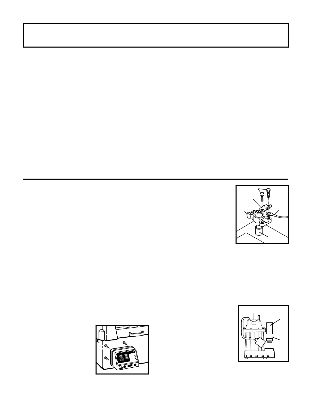
Tighten battery clamps
onto battery terminals.
With bolts and retainer
plates supplied, attach
BOLTS
BATTERY
CLAMP
CONTROL
PANEL
LEAD
BATTERY
TERMINAL
RETAINING
PLATE
RED control panel lead to POS-
ITIVE (+) battery clamp. Attach
BLACK control panel lead to
NEGATIVE (-) battery clamp.
The RED wire is supplied with
an in-line fuse to protect the
battery, pump and wiring should
a short, over-current or ground fault occur. If the fuse
must be replaced for any reason, it must be replaced
with one of the exact same rating. Failure to do so may
result in a fire hazard. If the leads are connected to the
wrong terminals, the REVERSE control panel indicator
will light. Reverse the leads and the 1 AMP fuse must
be replaced. If battery voltage is less than 11 volts DC,
the LOW control panel indicator will light. Recharge or
replace battery.
STEP
1
Remove cover from sump and disconnect the
primary sump pump from the discharge pipe.
Lift primary sump pump out of sump.
STEP
2
Attach control panel to
battery box with four
screws supplied.
Place 12-volt battery
(not included) into
battery box.
O
F
F
O
N
R
E
S
E
T
A
L
A
R
M
P
U
M
P
T
E
S
T
A
L
A
R
M
C
H
A
R
G
E
R
F
U
S
E
P
U
M
P
S
E
N
S
O
R
B
A
T
T
E
R
Y
C
H
A
R
G
E
D
B
A
T
T
E
R
Y
L
O
W
C
H
A
R
G
I
N
G
L
E
A
D
S
R
E
V
E
R
S
E
D
STEP
4
Thread male PVC
adapter into primary
pump discharge open-
ing. Cement a 3"-4"
PRIMARY
SUMP PUMP
piece of PVC pipe to adapter.
Use appropriate diameter piping.
MALE
ADAPTER
PVC
PIPE



 To Next Page