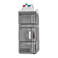
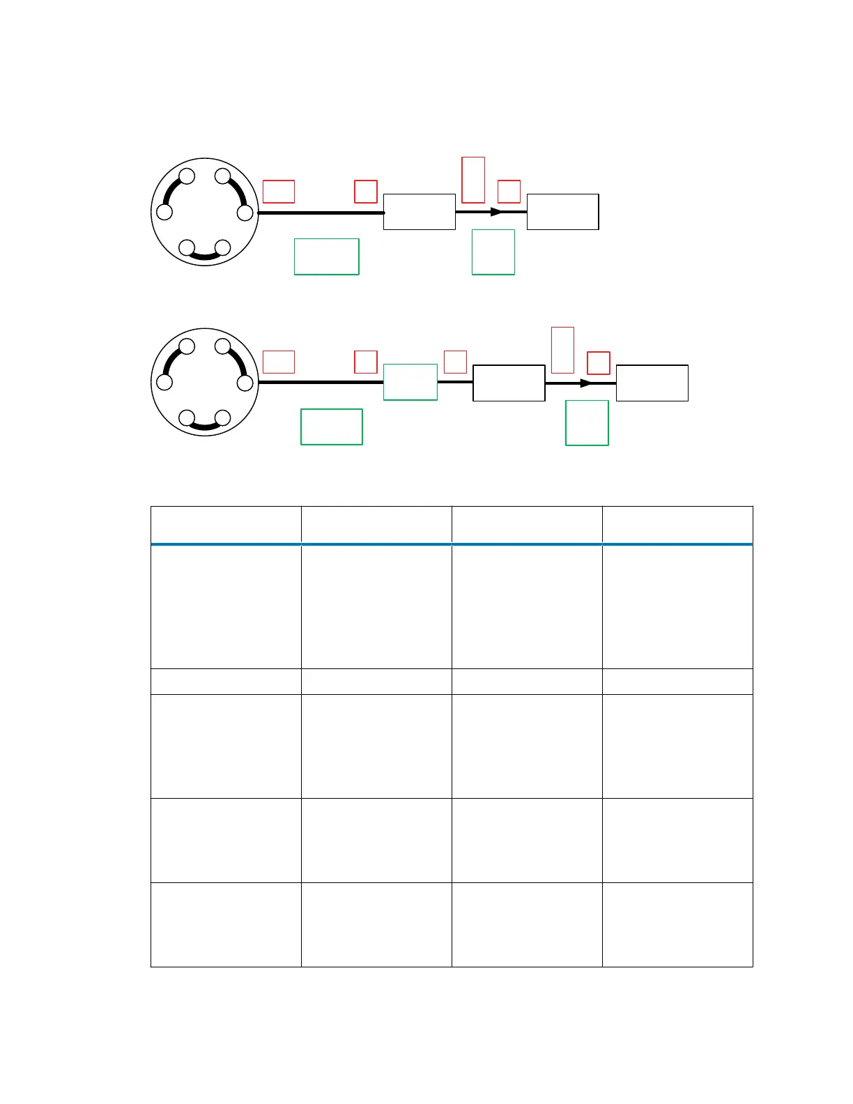
Figure 2–38: Connection diagrams for a CH-A fitted with a column stabilizer
F1*
Column
Stabilizer
F2
Column Detector
1
2
3
54
6
Injection
valve
T1
or
T2
F3
F1* F2
Detector
1
2
3
54
6
Injection
valve
F3
Column
Filter
F1
F1
or
F3
F1
or
F3
Sample manager
Sample manager
T1
or
T2
Column
Stabilizer
Table 2–3: Legend
Identifier Description Length Material
Column stabilizer Column-stabilizer
assembly that
connects the sample
manager's injection-
valve outlet to the
column inlet
32 cm (12.5 inches) SST
Filter Column filter (in-line) N/A SST
T1 Pre-configured tubing
assembly that
connects the column
outlet to the detector
inlet
Varies according to
detector setup
SST or PEEK
T2 Tubing assembly that
connects the column
outlet to the detector
inlet
Cut to length PEEK
F1* Stainless steel (gold-
plated) fitting with long
flats and two-piece
stainless steel ferrule
N/A SST (gold-plated
screw)
December 4, 2019, 715005052 Version 02 (previously released as Rev.B)
Page 55