FILENAME
DATE:
B.CREWS
DESCRIPTION:
PAGE
DRAWNBY:
RoomSensor
1
JOBNAME
02/05/03
G-RMSENS1.CDR
OE210,OE211,OE212,OE213
0.88“
TemperatureSensorResistance/VoltageChart
TempResistance*Voltage
FOhms@Input*
-10.............93333........4.620
-5...............80531........4.550
0...............69822........4.474
5...............60552........4.390
10..............52500........4.297
15..............45902........4.200
20..............40147........4.095
25..............35165........3.982
30..............30805........3.862
35..............27140........3.737
40..............23874........3.605
°
TempResistance*Voltage
FOhms@Input*°
45..............21094........3.470
50..............18655........3.330
52..............17799........3.275
54..............16956........3.217
56..............16164........3.160
58..............15385........3.100
60..............14681........3.042
62..............14014........2.985
64..............13382........2.927
66..............12758........2.867
68..............12191........2.810
TempResistance*Voltage
FOhms@Input*°
69..............11906........2.780
70..............11652........2.752
71..............11379........2.722
72..............11136........2.695
73..............10878........2.665
74..............10625........2.635
75..............10398........2.607
76..............10158........2.570
78..............9711..........2.520
80..............9302..........2.465
82..............8893..........2.407
TempResistance*Voltage
FOhms@Input*
84..............8514..........2.352
86..............8153..........2.297
88..............7805..........2.242
90..............7472..........2.187
95..............6716..........2.055
100............6047..........1.927
105............5453..........1.805
110............4923..........1.687
115............4449..........1.575
120............4030..........1.469
°
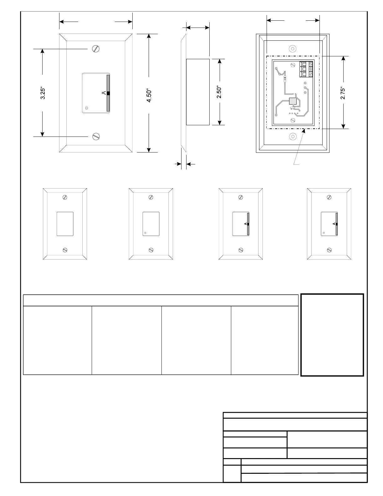
RoomSensorTypicalDimensions
*ChartNotes:
1.Usetheresistancecolumntocheckthethermistorsensorwhiledisconnectedfromthecontrollers(notpowered).
2.Usethevoltagecolumntochecksensorswhileconnectedtopoweredcontrollers.ReadvoltagewithmetersetonDCvolts.Placethe
"-"(minus)leadonGNDterminalandthe"+"(plus)leadonthesensorinputterminalbeinginvestigated.Ifthevoltageisabove5.08
VDC,thenthesensororwiringis"open."Ifthevoltageislessthan0.05VDC,thesensororwiringisshorted.
O
O O
A
A A
O
O O
R
R R
L
L L
M
M M
E
E E
E
E E
C
C C
W
W W
R
R R
R
R R
OVR
OVR OVR
0.25“
TMP
GND
AUX
OUT
2.00“
WallCut-OutDimensions
WhenSensorIsToBe
MountedWithout
HandyBox(ByOthers)
2.75“
OE210 OE211
OE212
OE213
RoomSensor-Plain
RoomSensor
WithOverride
RoomSensor
WithSetpointAdjust
RoomSensor
WithSetpointAdjust
&Overide
Caution:
TheRoomSensorIs
SuppliedWithAMylar
FilmCoatingOnThe
SensorPlateThat
ProtectsThePlateFrom
MarringAndDamage
DuringShipmentAnd
Installation.After
InstallationOfThe
SensorIsCompleted,
ThisMylarFilmMustBe
RemovedForProper
SensorOperation.