Do you have a question about the Wavetek MS1200 and is the answer not in the manual?
Information on extended warranties and service contracts available for equipment.
Steps required to obtain a return authorization number before sending equipment for repair.
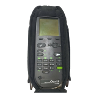
Description of the MS1200 Signal Level Meter, its design, and display features.
Overview of the keypad's components including soft keys, power key, mode selection, enter, alphanumeric, and shift keys.
Detailed explanation of the function of each mode selection key, including Installation and Level modes.
Description of Full Scan, Navigator, Enter, Alphanumeric, and Shift keys.
Explanation of Configure Mode and Auto Reference as secondary functions accessible via the Shift key.
Details on Snap Shot, Clear, Backlight, Positive/Negative, Help, and Print functions.
Description of the Title Bar and its role in displaying current mode and icons.
Explanation of indicators appearing above the title bar: Shift, Low Battery, and RF Synthesizer.
Description of the status bar battery meter and how soft key icons indicate available functions.
How to identify active/inactive lists and use scroll bars for navigation.
How to enter values into the edit box and confirm entries.
How to travel to different modes using the Navigator screen and its icons.
Introduction to the Configure mode for setting preferences and building channel plans.
Dividing configuration settings into GLOBAL, MEASUREMENTS, and CHANNEL PLAN.
How to print a comprehensive report of all configurable settings.
Personalizing the device by setting the operator name for report printouts.
Adjusting LCD contrast and configuring automatic shutoff and backlight timeouts.
Manual control of the backlight and indicators for its status.
Setting up the printer for use with the microStealth, including serial interface requirements.
Required settings for printer communication: Baud Rate, Data Bits, Stop Bits, Parity, Flow Control.
CLONE function for copying configurations and DIAGNOSTICS for hardware checks.
Resetting all stored preferences to factory presets, noting data loss.
Exercising LCD pixels for test purposes by cycling through different display states.
Options to include audio carriers and scrambled channels in the full scan.
How to edit limits for different test points like Subscriber Drop or TAP.
Changing the name of USER DEFINED test points using the edit box.
How to selectively enable or disable individual limits for a test point.
Selecting NTSC/PAL video signals and defining channel order for tuning.
Procedure to identify and generate a customized channel plan for the cable system.
Steps for naming, selecting a foundation, and setting stop frequency for plan building.
How to modify various parameters for each channel in the plan.
Verifying and enabling/disabling channels for measurement within the channel plan.
Setting parameters like Type, Frequency, Channel Number, and Label for each channel.
Explanation of channel types (TV, DUAL, SNGL), frequency, and channel number range.
Using labels for identification and organizing channels into packages.
Setting for scrambled channels and audio offset for TV/DUAL types.
Specifying which carriers to measure for TILT in the TILT screen.
Selecting up to six channels for TILT measurement and displaying their numbers.
Organizing channels into groups or tiers for installation checks.
Selecting and enabling/disabling packages, and understanding the impact on channels.
Procedure for changing the name of a channel package using the edit box.
Easily copying a channel plan from one microStealth unit to another via cable.
Guidance on learning microStealth by using it, covering measurement modes and controls.
Checking installed channels against limits and verifying subscriber packages.
Choosing specific channel packages for evaluation during an installation check.
Determining the test point (e.g., Subscriber Drop, TAP) to apply appropriate limits.
Summary of limit checks for all channels in selected packages, indicating PASS/FAIL.
Understanding the PASS/FAIL indicator and actual values for each limit.
Information displayed for each channel: number, label, level, package, and overall pass/fail.
Using the indicator to quickly determine channel status and identify failure reasons.
Indicators for adjacent channel and video level issues (too high/low).
Indicators for DVA (Digital Video Analog) levels being too high or too low.
Display of video, audio carrier levels, and DVA for the selected channel.
Generating a comprehensive report of installation results including subscriber information.
Measuring signal level of a specific channel or frequency numerically and on an analog meter.
Adjusting the analog bar meter's reference level or auto-setting it.
Navigating through channels or tuning to specific frequencies using keys.
Freezing the current measurement, retained even if disconnected.
Printing the entire screen content to a serial printer.
Indicators for Over-range and Under-range signal levels.
Displaying a spectral graph of all carriers in the channel plan.
Using a marker to select channels and view their frequency and level.
Modifying the reference level and scale for optimal viewing of carrier levels.
Magnifying specific parts of the graph using zoom soft keys.
Verifying carrier levels against limits by selecting the test point.
Sequencing through test points to view overall limit check summary on the graph.
Understanding how limit check results apply to displayed channels and hash areas.
Indicators for measurement too high/low and adjacent channel errors.
Freezing scan measurements, retained if disconnected, released on mode change.
Balancing amplifiers using TILT mode, accessed via Navigator, displays TILT carriers.
Navigating carriers and selecting low/high pilot carriers for tilt measurement.
Modifying reference level and scale settings for the tilt graph.
Freezing the tilt measurement, retained if disconnected, released on mode change.
Displaying up to six video carriers in the SCAN mode.
Modifying the reference level setting for the scan graph.
Adjusting the scale for optimal viewing of carrier levels in the scan graph.
Verifying carrier levels against limits by selecting test points and viewing hash areas.
Checking if SCAN carriers are within limits using the PASS/FAIL indicator.
Freezing scan measurements, retained if disconnected, released on mode change.
Accessing on-line user assistance and context-sensitive help screens.
Understanding descriptions of soft key functions next to icons in help screens.
Viewing device information like model, serial number, firmware version, and calibration date.
Reaching Wavetek's Technical Support via phone or Internet for assistance.
Contacting Customer Service for general inquiries and international representation.
Details on frequency range, accuracy, resolution bandwidth, and tuning resolution.
Specifications for level measurement range, resolution, and accuracy.
Scan rate, number of channels, dimensions, weight, operating temperature, and water resistance.
Battery life, charge time, and standard accessories like charger and battery cartridge.
Information on optional frequency extensions, carrying cases, and field-replaceable batteries.
Instructions for removing, replacing, and installing the MS1200 battery pack.
Procedure for recharging the battery pack using the AC adapter.
Recommendations for maximizing battery life, including auto-shutoff settings.
Description of the 3-pin stereo connector for RS232 serial data interchange.
Details of pin assignments (TXD, RXD, GND) for the interface port.
Wiring diagram for connecting the microstealth to a PC via stereo plug and DB9 connector.
Wiring diagram for connecting the microstealth to a standard printer via stereo plug and DB25 connector.
Wiring diagram for direct connection between two microstealth units.
Wiring diagram for connecting to a Citizen printer via stereo plug and 26-pin connector.
| Brand | Wavetek |
|---|---|
| Model | MS1200 |
| Category | Cable Tester |
| Language | English |