EasyManua.ls Logo

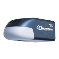
Wayne-Dalton Prodrive 3221C User Manual

Wayne-Dalton Prodrive 3221C
48 pages
To Next Page IconTo Next Page
Page #1 background imageLoading...
Page #1 background image
®
GARAGE DOOR OPENER
INSTALLATION INSTRUCTIONS AND OWNER’S MANUAL
Chain/ Belt Drive
Models: 3220C, 3221C, 3222C, 3224C, 3320B, 3322B, 3324B
3220C-Z, 3221C-Z, 3222C-Z, 3224C-Z, 3320B-Z, 3322B-Z, 3324B-Z
IMPORTANT NOTICE!
Read the enclosed instructions carefully before installing/operating
this garage door opener. Pay close attention to all warnings and
notes. This manual MUST be attached to the wall in close proximity
to the garage door.
Copyright 2008 Wayne-Dalton Corp. Part No. 325809 Rev.5 7/16/2008
FOR RESIDENTIAL SECTIONAL OVERHEAD GARAGE DOORS ONLY!
DO NOT USE ON ONE PIECE DOORS!
IMPORTANT! THE DOOR AND OPENER WILL NOT FUNCTION PROPERLY UNTIL
INFRARED SAFETY SENSORS ARE INSTALLED AND PROPERLY ADJUSTED!
GARAGE DOORS & OPENERS

Table of Contents

Question and Answer IconNeed help?

Do you have a question about the Wayne-Dalton Prodrive 3221C and is the answer not in the manual?

Wayne-Dalton Prodrive 3221C Specifications

General IconGeneral
Horsepower1/2 HP
TypeChain Drive
Voltage120V
Frequency60 Hz
Speed7.5 inches per second
Remote Controls Included2
SecurityRolling Code Technology
Warranty1 year

Summary

Pre-Installation Procedures

Pre-Installation Inspection

Check garage door balance and smooth operation before installation. Adjust if necessary.

Test Door Operation

Perform two tests to ensure door is balanced and operating correctly for safety.

Important Installation Guidelines

General Installation Precautions

Crucial safety and installation steps to follow before starting the opener installation.

Step 1: Attaching Opener to Rail

Align Driver Gear and Sprocket

Properly align the driver gear with the sprocket/coupling cogs in the rail assembly.

Step 2: Front Wall Bracket Installation

Step 5: Mounting the Opener

Step 6 & 7: Door Bracket and Light Installation

Step 8: Wired Wall Station Installation

Step 9: Wireless Wall Station Installation

Step 11: Wired Infrared Safety Sensor Installation

Mount Safety Sensor Brackets

Mount wall brackets at the same height, no more than 5 inches above the floor.

Route and Connect Sensor Wiring

Route sensor wires and connect them to the opener, observing polarity.

Step 14 & 15: Opener Connection

Connect Opener to Outlet

Plug the opener into a properly grounded 3-prong, 120-volt outlet.

Step 16: Safety Sensor Alignment

Align Safety Sensor Beams

Align sensors by moving units until the alignment light on the receiving unit illuminates.

Step 17: Trolley Close Position

Set Trolley Close Position

Verify and adjust trolley close position to 11-13 inches using the close travel adjustment screw.

Step 18: Connecting Door Arm

Attach Door Arm to Door Bracket

Connect the upper and lower door arms to the door bracket using clevis pins and bolts.

Step 19 & 20: Travel Limit Adjustments

Set Door Close Travel

Adjust close travel so door reverses upon contact with a 2x4 on the floor.

Step 21 & 22: Obstruction Tests

Contact Obstruction Test

Ensure door reverses upon contacting a 1 1/2" object or 2x4 on the floor.

Safety Sensor Obstruction Test

Verify door reverses when a 6" object blocks safety sensors.

Step 23 & 24: Keyless Entry Setup

Door Bracket Mounting for Series

Safety Instructions and Operation

General Safety Precautions

Read and follow all instructions. Keep children away. Keep door in sight.

HomeLink® Programming

Adjustments

Opening and Closing Force Adjustment

Adjust force to ensure safe reversal on closing and proper stopping on opening.

Contact Obstruction Sensing Adjustment

Set closing direction to reverse upon contact with a 2x4 on the floor.

Programming Wall Stations and Transmitters

Troubleshooting Guide

Common Opener Symptoms and Solutions

Diagnose and fix issues like no power, opener not working, or door reversal problems.

Limited Warranty Information

Related product manuals