64659-001 REV. A 07/06/18
11
It is recommended that Table 2, Table 3, and Table 4be used to determine the size pipe to use from the
meter to the burner. The building structure should not be weakened by installation for the gas piping.
The piping should not be supported by the other piping, but should be firmly supported with pipe hooks,
straps, bands or hangers. Butt or lap welded pipe should not be bent. Note: Each elbow, union, and tee
adds approximately 2.5 feet of pipe.
The gas piping should be so installed as to prevent an accumulation of condensation and must be
protected against freezing. A horizontal pipe should be pitched so that it grades toward the meter and
is free from sags. The pipe should not be run through or in an air duct. The appliance and its individual
shutoff valve must be disconnected from the gas supply piping system during any pressure testing of the
system at test pressure over 1/2 psig (3500 PaG). The appliance must be isolated from the gas supply
piping system by closing its individual manual shutoff valve during any pressure testing of the gas supply
piping system at test pressures equal to or less than 1/2 psig (3500 PaG).
Pipe Sizing Chart for Natural Gas (0-0.5 psi) with Straight Schedule 40 Metal Pipe
This table is based on 0-0.5 psi inlet pressure, specific gravity of 0.6, and a pressure loss of 0.5” w.c..
Maximum Capacity of Pipe Size in Btu per Hour
Table 2 - Natural Gas Pipe Capacity
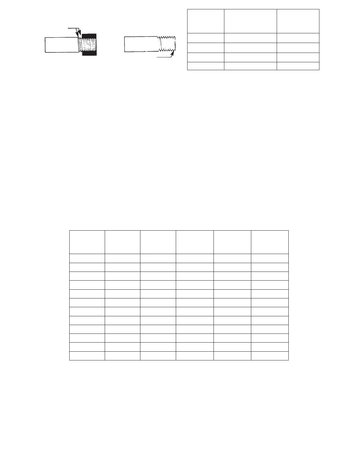
Effective Length of
Thread
Inch (mm)
Overall Length
of Thread
Inch (mm)
Table 1 - Pipe Thread Length
Figure 5 - Proper Piping Practice