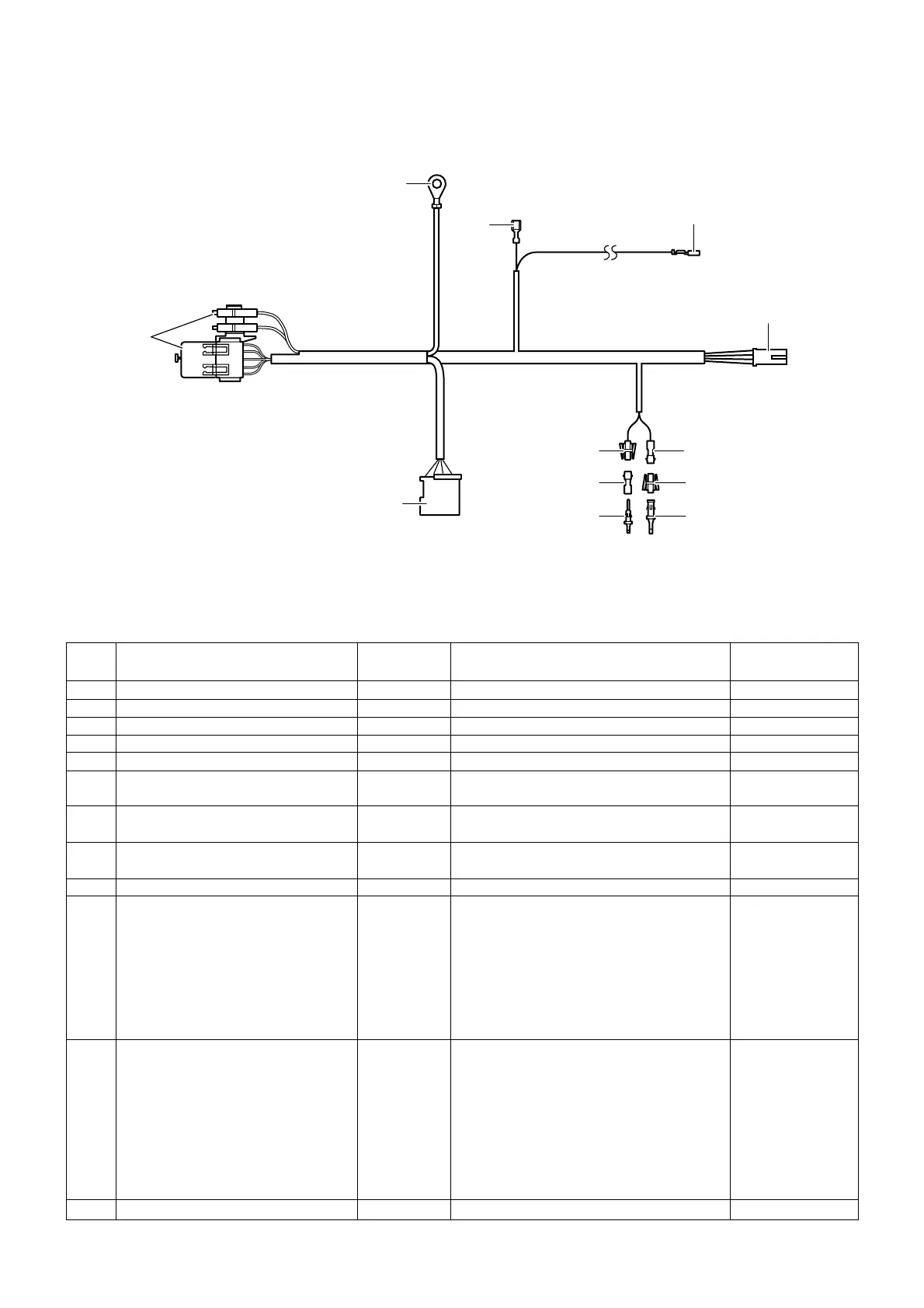
3. Connection diagram
Retrofit/Installation Kit no. 82 30 0 020 941 Date: 05.2000
Installation Instructions no. 01 29 0 021 305
EN/26
1
2
3
4
A
B
C
D
E
F
G
H
1-pole socket housing
Socket contact
1-pole pin housing
Pin contact
Relay base and fuse holder
Ring terminal A8 (terminal 30)
Joint connector contact (terminal 31)
1-pole socket contact
(activation of supplementary heater)
4-pole socket housing
1-pole pin housing (blower activation)
1-pole socket housing
(blower activation)
6-pole socket housing
–––––
–––––
–––––
–––––
–––––
red 2.5 mm
2
brown
1.0 mm
2
black
0.5 mm
2
–––––
green/red
2.5 mm
2
green/yellow
2.5 mm
2
–––––
Mating connector to F
for socket housing (1)
Mating connector to G
for socket housing (3)
Relay carrier behind glove box
Terminal 30 connecting point at fuse
holder behind glove box
Joint connector box behind glove box
6-pole socket housing of the park heating
Timer (optional)
Vehicles with IHKA from start of produc-
tion and vehicles with IHR from 9.98:
connect with outgoing green/yellow lead
coming from fuse F28
only vehicles with IHR to 9.98:
connect with outgoing yellow/green lead of
connector X18722, Pin 1 coming from the
vehicle wiring harness
Vehicles with IHKA from start of produc-
tion and vehicles with IHR from 9.98:
connect with outgoing green/yellow lead
coming from heater or air conditioner
operating unit A11, connector X608, Pin 2
only vehicles with IHR to 9.98:
connect with outgoing yellow/green lead
coming from connector X905, Pin 4 of the
blower switch S75
Receiver A128 in footwell, right
X1*, X2* and X3*
X13020
X219
X764/1
X10130
X4*
X5*
X18830
Item Designation
Cable colour/
cross-section
Connection point/installation
location in vehicle
Code designation/
Pin