Retrofit/Installation Kit no. 82 30 0 020 941 Date: 05.2000
Installation Instructions no. 01 29 0 021 305
Only vehicles with IHKA (automatic heating
and air conditioning) from start of production
and vehicles with IHR (integrated heating
control) from 9.98:
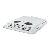
Cut green/yellow cable (1) at a suitable place
behind the natural-coloured 6-pole connector
X608 (2).
Provide the green/yellow cable end (1) coming
from fuse holder A47. fuse F28, with a socket
contact and socket housing (5) and connect with
branch cable F (4), cable colour green/red.
Provide green/yellow cable end (1) coming from
IHKA or IHR operating unit A11, connector X608,
Pin 2 (2), with pin contact and pin housing (6)
and connect with branch cable G (3), cable
colour green/yellow.
5. Install park heating wiring harness and connect it
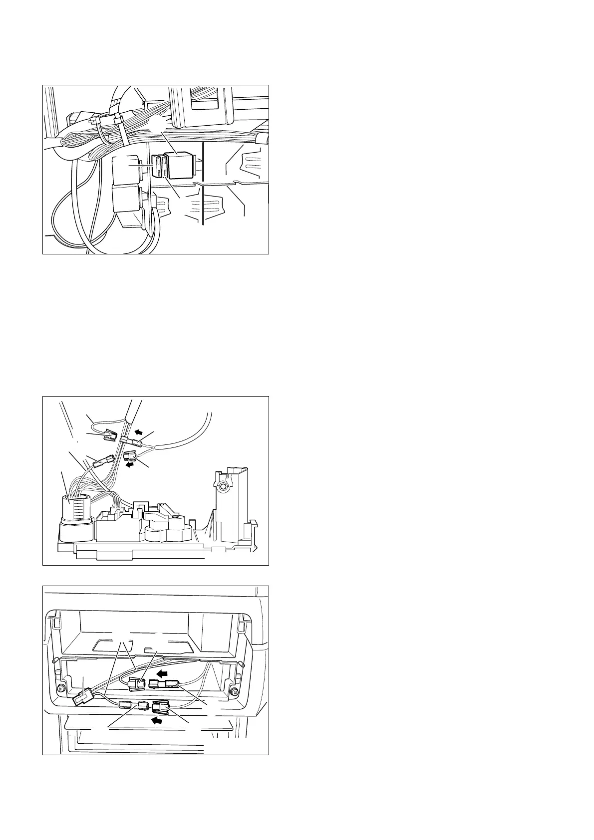
Only vehicles with IHR (integrated heating
control) to 9.98:
Cut yellow/green cable (1) of connector X905 (6)
coming from the blower switch S75, Pin 4.
Provide the yellow/green cable end (1) of
connector X905 (6) coming from the blower
switch S75, Pin 4, with a pin contact and pin
housing (2) and plug this together with branch
cable G, (4) cable colour green/yellow.
Provide yellow/green cable end (1) coming from
the vehicle wiring harness, connector X18722,
Pin 1, with a socket contact and socket housing
(3) and plug this together with branch cable F (5),
cable colour green/red.
Only vehicles with IHR (integrated heating
control) to 9.98:
Fuse 1A (2) must be plugged on to fuse holder
A1* (cable cross-section 0.5 mm
2
).
Fuse 25A (1) must be plugged on to fuse holder
A2* (cable cross-section 2.5 mm
2
).
Only vehicles with IHKA (automatic heating
and air conditioning) from start of production
and vehicles with IHR (integrated heating
control) from 9.98:
Fuse 1A (2) must be plugged on to fuse holder
A1* (cable cross-section 0.5 mm
2
).
Fuse 5A (1) included in the installation kit) must
be plugged on to fuse holder A2* (cable
cross-section 2.5 mm
2
).
All vehicles:
Clip in relay base X1* (3) with fuse holder A1* (2)
and A2* (1) behind the glove box at the free
place at the relay carrier or fasten with cable
straps.
Install branch cables F and G, cable colours
green/red and green/yellow, to installation loca-
tion of the heater/air conditioner operating unit.
EN/28