Rheostatic Braking
13-2 | CFW501
13
U
d
rated
DC link voltage (U
d
) (P0004)
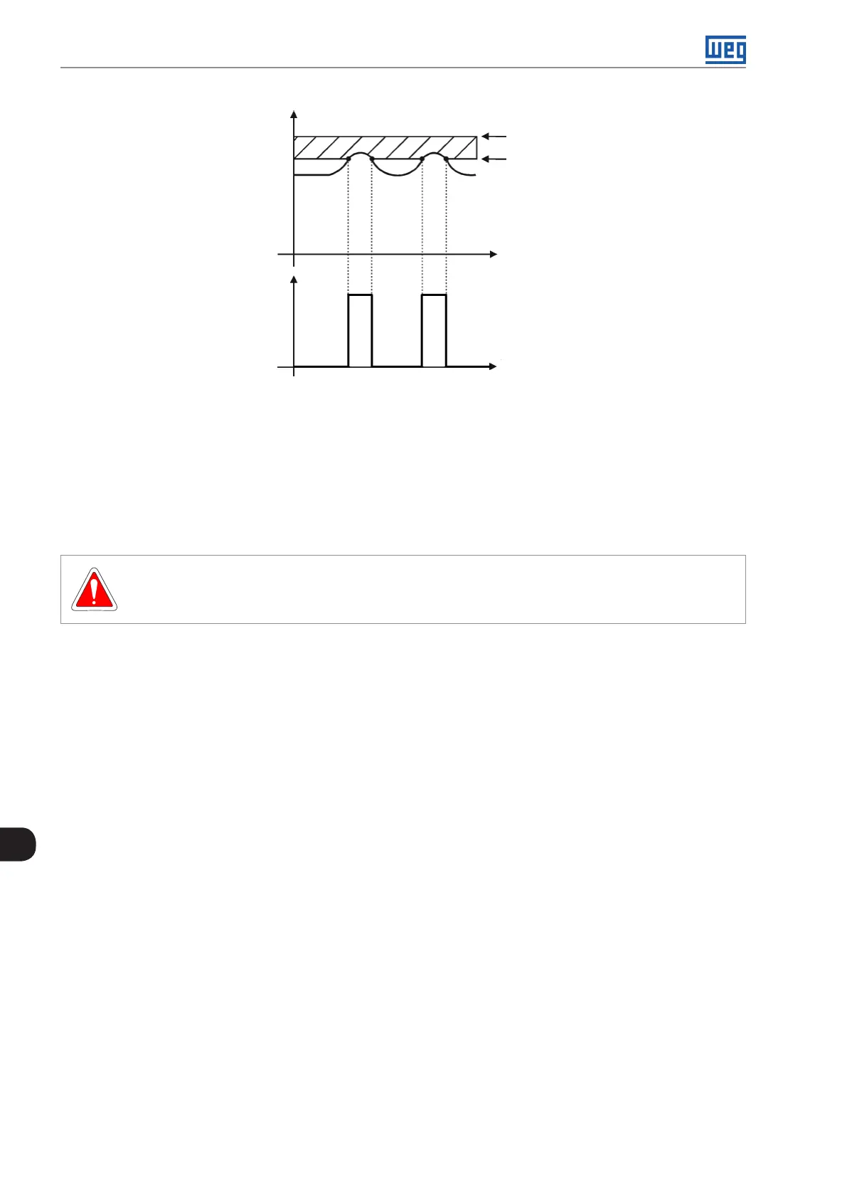
F0022 - Overvoltage
Rheostatic braking
actuation
Time
Time
U
d
U
d
P0153
Braking resistor
voltage (BR)
Figure 13.1: Rheostatic braking actuation curve
Steps to enable the rheostatic braking:
With the inverter powered down, connect the braking resistor (refer to the user’s manual, item 3.2 - Electric
Installations).
Setting P0151 for the maximum value: 410 V (P0296 = 0), 810 V (P0296 = 1) or 1200 V (P0296 = 2), according
to the situation, in order to prevent the actuation of the DC link voltage regulation before the rheostatic braking.
DANGER!
Be sure the inverter is OFF before handling the electric connections and read carefully the installation
instructions of the user's manual.

 Loading...