General Information
CFW501 | 2-1
2
2 GENERAL INFORMATION
2.1 ABOUT THE MANUAL
This manual presents information necessary for the configuration of all the functions and parameters of the frequency
inverter CFW501. This manual must be used together with the user’s manual of the CFW501.
The text provides additional information so as to make the use and programming of the CFW501 easier in certain
applications.
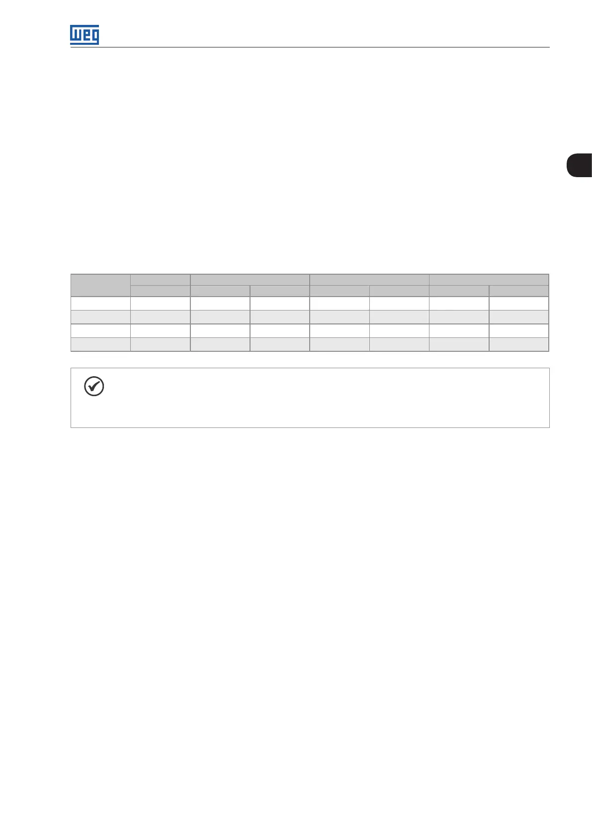
The standard value for the parameters related to speed described in this manual assumes a standard 4-pole
motor, that is, with synchronous speed of 1500 rpm (50 Hz) or 1800 rpm (60 Hz). Table 2.1: Setting of the speed
parameters on page 2-1 shows the setting suggested of those parameters for other number of poles. Furthermore,
parameter P0402 must be set with the data on the motor nameplate; if not available, use the rated speed.
Table 2.1: Setting of the speed parameters
Number of
Poles
P0133 P0134 and P0145 P0146 P0147
50 Hz 60 Hz 50 Hz 60 Hz 50 Hz 60 Hz
2 180 rpm 3000 rpm 3600 rpm 2000 rpm 2400 rpm 1000 rpm 1200 rpm
4 90 rpm 1500 rpm 1800 rpm 1000 rpm 1200 rpm 50 0rpm 600 rpm
6 60 rpm 1000 rpm 1200 rpm 667 rpm 800 rpm 333 rpm 400 rpm
8 45 rpm 750 rpm 900 rpm 500 rpm 600 rpm 250 rpm 300 rpm
NOTE!
“The specific HVAC functions present on the CFW501 can only be activated with the connection of
the HVAC plug-in module (CFW500-CRS485). Other plug-in modules can be used, but in this case
the HVAC application must be turned off by means of parameter P1001.”
2.2 TERMINOLOGY AND DEFINITIONS
2.2.1 Terms and Definitions Used
I
nom
: inverter rated current by P0295.
Overload Duty: in the CFW501 there is no difference in the operating duty between “Light - Normal Duty” (ND)
and “Heavy - Heavy Duty” (HD). Thus, the overload duty adopted for the CFW501 is equivalent to the HD standard,
that is, the maximum overload current is 1.5 x I
nom
for one minute of continuous operation.
Rectifier: input circuit of the inverters that transforms the input AC voltage into DC. It is formed by high-power
diodes.
IGBT: insulated Gate Bipolar Transistor - basic component part of the output inverter bridge. It works as an
electronic switch in the saturated (closed switch) and cut-off (open switch) modes.
DC Link: intermediary circuit of the inverter; voltage in direct current obtained by rectifying the power supply
alternate voltage or external supply; it supplies the output inverter bridge with IGBTs.
Pre-Charge Circuit: charges the capacitors of the DC link with limited current, avoiding current peaks in the
inverter power-up.
Braking IGBT: it works as a switch to turn on the braking resistor. It is controlled by the DC link level.

 Loading...