HMI and Basic Programming
4-2 | CFW501
4
4.2 INDICATIONS ON THE HMI DISPLAY
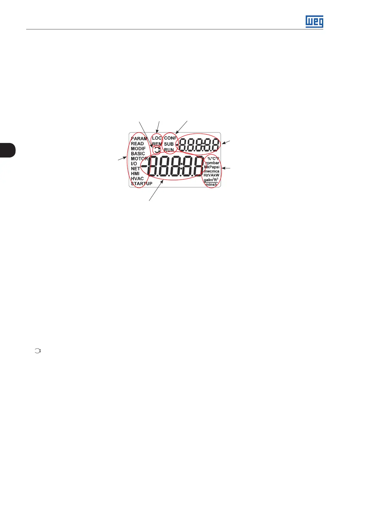
The information shown on the HMI LCD display is divided into five fields: menu, status, secondary display, unit,
and main display. Those fields are defined in Figure 4.2: Display areas on page 4-2. The main and secondary
display set allows alternating the focus to scroll the parameter number or parameter value according to levels 2
and 3 of the parameterization mode, respectively.
Inverter status
Local/Remote
(command
and reference
source)
Secondary display
Unit of measurement
(it refers to the value
of the main display)
Menu (to select the
parameter groups) –
only one parameter
group is shown at a
time.
Main display
Forward/Reverse
Figure 4.2: Display areas
Parameter groups available in the field Menu:
PARAM: all parameters.
READ: read only parameters.
MODIF: parameters modified in relation to the factory default.
BASIC: parameters for basic application.
MOTOR: parameters related to the motor control.
I/O: parameters related to digital and analog inputs and outputs.
NET: parameters related to the communication networks.
HMI: parameters to configure the HMI.
HVAC: parameters related to HVAC applications.
STARTUP: parameters for oriented Start-up.
Status of the inverter:
LOC: command source or local references.
REM: command source or remote references.
: direction of rotation by means of arrows.
CONF: CONFIG status active.
SUB: undervoltage.
RUN: execution.

 Loading...