About the CFW501
3-2 | CFW501
3
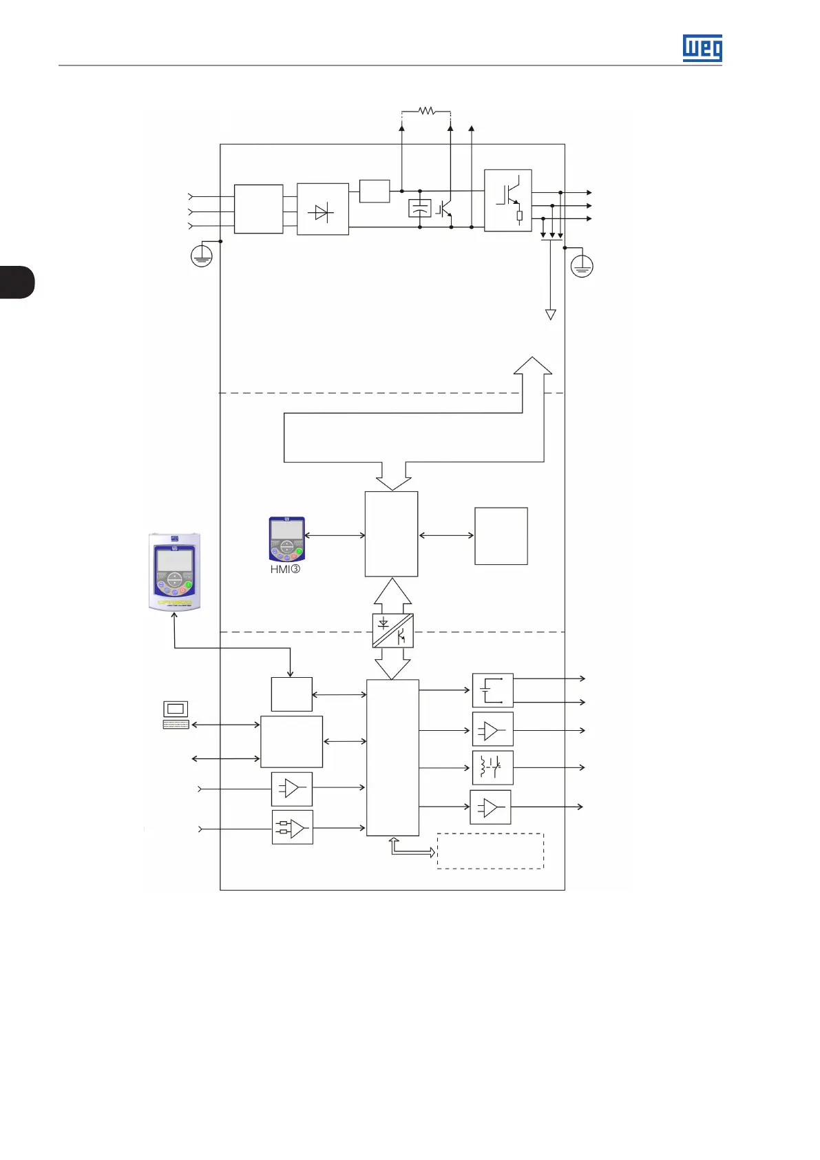
Analog input
(AI1 and AI2)
(*)
Digital inputs
(DI1 to DI4)
(*)
Power supplies for electronics and interfaces
between power and control
RS-485
PC
POWER
Single-phase
/ th re e -p h as e
rectifier
Internal
RFI filter
Motor
U/T1
V/T2
W/T3
DC+ DC-BR
DC-Inverter
with IGBT
transistors
and current
feedback
Power
supply
R/L1/L
S/L2/N
T/L3
= DC link connection
= Braking resistor connection
Pré-
carga
Software WLP
SUPERDRIVE
(*)
MODBUS
DC link capacitor bank
Braking IGBT (available in
Inverters CFW501...DB...)
HMI
CPU
32 bits
"RISC"
EEPROM
(memory)
User’s
plug-in
card
Interface
RS-485
Analog output
(AO1)
(*)
Supply 24 V
Supply 10 V
Digital output
DO1 (RL1) and
DO3 (RL2)
Digital output
DO2 (TR)
(*)
HMI
(remote)
Voltage
feedback
(**)
PE
PE
Memory card (MMF)
Accessory
CONTROL
CONTROL
PLUG-IN RS-485
= Human-machine interface
(*) The number of inputs and outputs (analog and digital) may vary according to the used plug-in module. For further information,
refer to the installation, configuration and operation guide of the accessory with plug-in module used.
(**) Not available in mechanics A.
Figure 3.1: CFW501 block diagram

 Loading...