30 | Flameproof motors
2
cos121.1cos1
25,18836
1
1
1.1
2
alfaalfaK
RPMDPMT
N
FR
e
e
K
I
DPMTDPMV
alfa
alfaMI
alfaMI
This is a general calculation. Consult
the belt’s manufacturer for an accurate
value.
Always use pulleys duly balanced.
Avoid, in all cases, oversized keys as
these can cause unbalancing. In case
these instructions are not followed
accordingly, vibration levels will occur.
5.1.5.4 COUPLING ARRANGEMENT
FOR SLEEVE BEARING - AXIAL
CLEARANCE
Motors fitted with sleeve bearings should be
directly coupled to the driven machine or even
using a gearbox. Pulley/belt coupling is not
recommended.
These sleeve bearing motors have three
identification marks on the shaft drive end. The
central mark is the indication of the magnetic
center; the other two outer marks indicate the
allowable limits for the rotor axial displacement.
Figure 5-16 - Sleeve bearing shaft alignment
The Figure 5-16 shows part of the bearing frame
where the arrow indicates the magnetic center and
the three marks on the shaft.
When coupling the motor, the following aspects
must be considered:
- Bearing axial clearance which is shown on the
table below for each bearing size.
- Axial displacement of the driven machine, if
any.
- Maximum axial clearance allowed by the
coupling.
Table 5-3 – Standard clearances applied to sleeve
bearings
Clearances applied to sleeve bearings for flameproof
motors supplied by WEG
(1) This is a standard value. Other values can be used
according to the motor project.
The motor must be coupled in such a way that the
arrow attached to the bearing frame be positioned
exactly on the central mark while motor is in
operation.
During motor starting or even under operation,
rotor should move freely between the two external
slots if the driven machine creates any axial force
on the motor shaft. Under no circunstance, motor
can operate continuously with axial force on the
bearing.
Rotor is not self alligned.
Sleeve bearings normally used by WEG are not
designed to withstand axial forces continuously.
The driven machine should have its axial end play
limited as necessary to prevent applying any axial
load to the motor sleeve bearings.
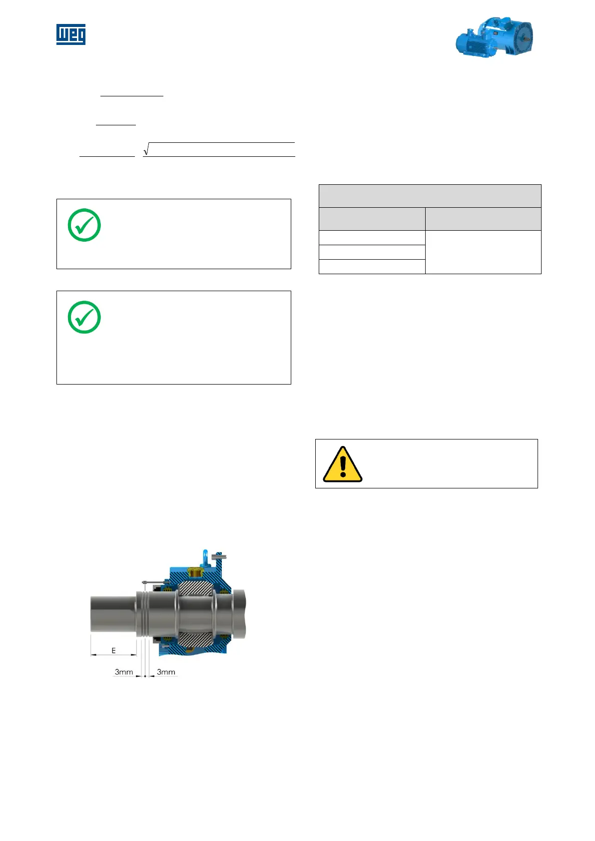
The Figure 5-17 shows part of the drive end
bearing highlighting a basic configuration of the
shaft/bearing set as well as axial clearances.