Flameproof motors | 53
Figure 8-11 – Disconnecting the terminal
RE-ASSEMBLY THE ENDSHIELD
When proceeding to the re-assembly, care must be
taken with the re-connection of the terminals.
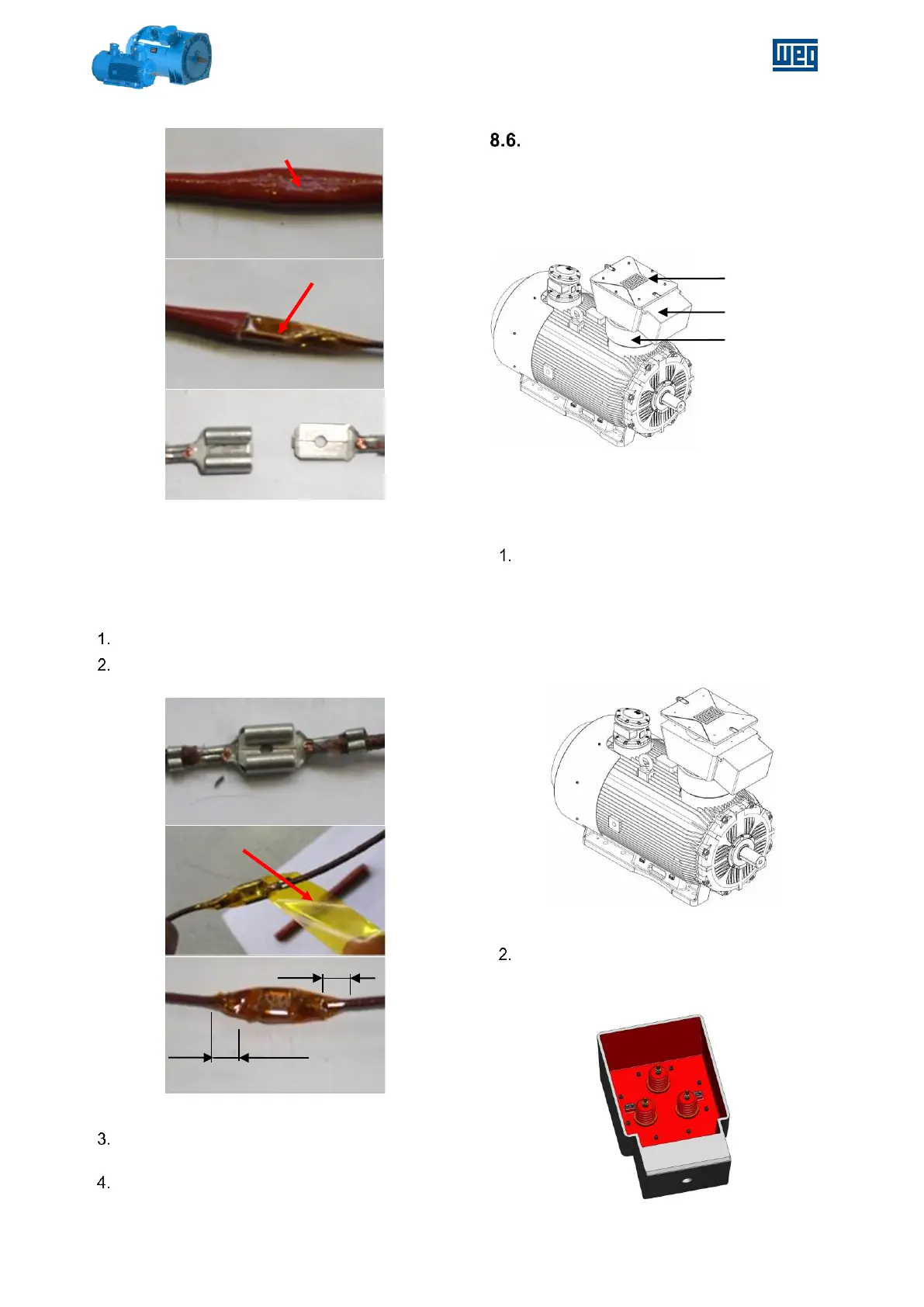
Connect both sides of the terminal.
Insulate the connection with two layers of
Kapton® tape
Figure 8-11 - Connecting and insulating the terminal
Cover the insulated connection with the
silicone sleeve.
Complete the endshield assembly.
POWER TERMINAL BOX
ROTATION PROCEDURE
For motors equipped with Power Terminal Box –
PTB, located at top of the motor with cable entries
from drive end side.
Figure 8-12 - Example of Motor with PTB with cable
entries from DE side
Procedure to rotate the Power Terminal Box
(example for 90º CCW seen from top of PTB):
Remove the PTB cover:
a. Unbolt the PTB cover - 8 bolts;
b. Install a magnet in the center of PTB
cover;
c. Pull the magnet to remove the PTB
cover;
Figure 8-13 - PTB cover removed
Rotate the PTB with rotate device;
a. Unbolt the PTB – remove the 8 bolts
inside terminal box;
Figure 8-14 – Inside view of PTB