10
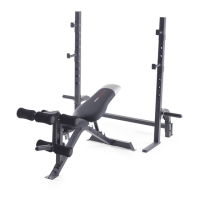
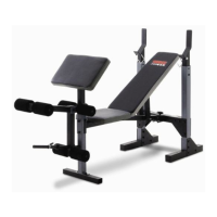
ADJUSTING THE UPRIGHTS
T
o adjust the Uprights (1), unscrew the M10 x 65mm
Adjustment Knobs (30) and slide the Uprights to the
d
esired position. Re-tighten the Adjustment Knobs
into the Upright Bases (7) and the Uprights.
USING THE BARBELL HOOKS
To change weights while your barbell (not included) is
on the Uprights (1), secure the barbell with the
Barbell Hooks (13, 21 [not shown]). To do this, rotate
the Barbell Hooks over the barbell. This will reduce
the possibility of the barbell tipping while you are
changing weights.
7
1
13
1
30
WARNING: Always set both
Uprights (1) at the same height. Make sure the
M10 x 65mm Adjustment Knobs (30) are fully
tightened into the Upright Bases (7) and the
Uprights.
6
8
37
39
33
3
Anchor
Hole
Anchor
Hole
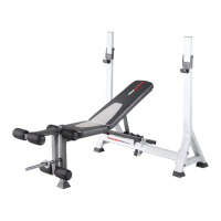
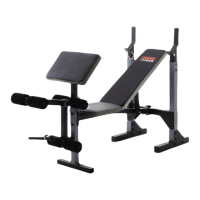
STORING THE WEIGHT BENCH
To store your weight bench, remove the M10 x 60mm
Adjustment Knob (33) and the Ring Pin (39) from the
Crossbar (3). Lift the Front Leg (8) as far as it will go.
Reinsert the Ring Pin into the bracket on the
Crossbar; the Ring Pin will prevent the bench from
unfolding.
Note: The Backrest (6) must be adjusted
to one of the incline positions (see ADJUSTING
THE BACKREST, on page 9).
CAUTION: To fold the weight
bench, the anchor holes in the Stabilisers (37)
must be at least 50 cm (20 in.) from the wall.
37
7
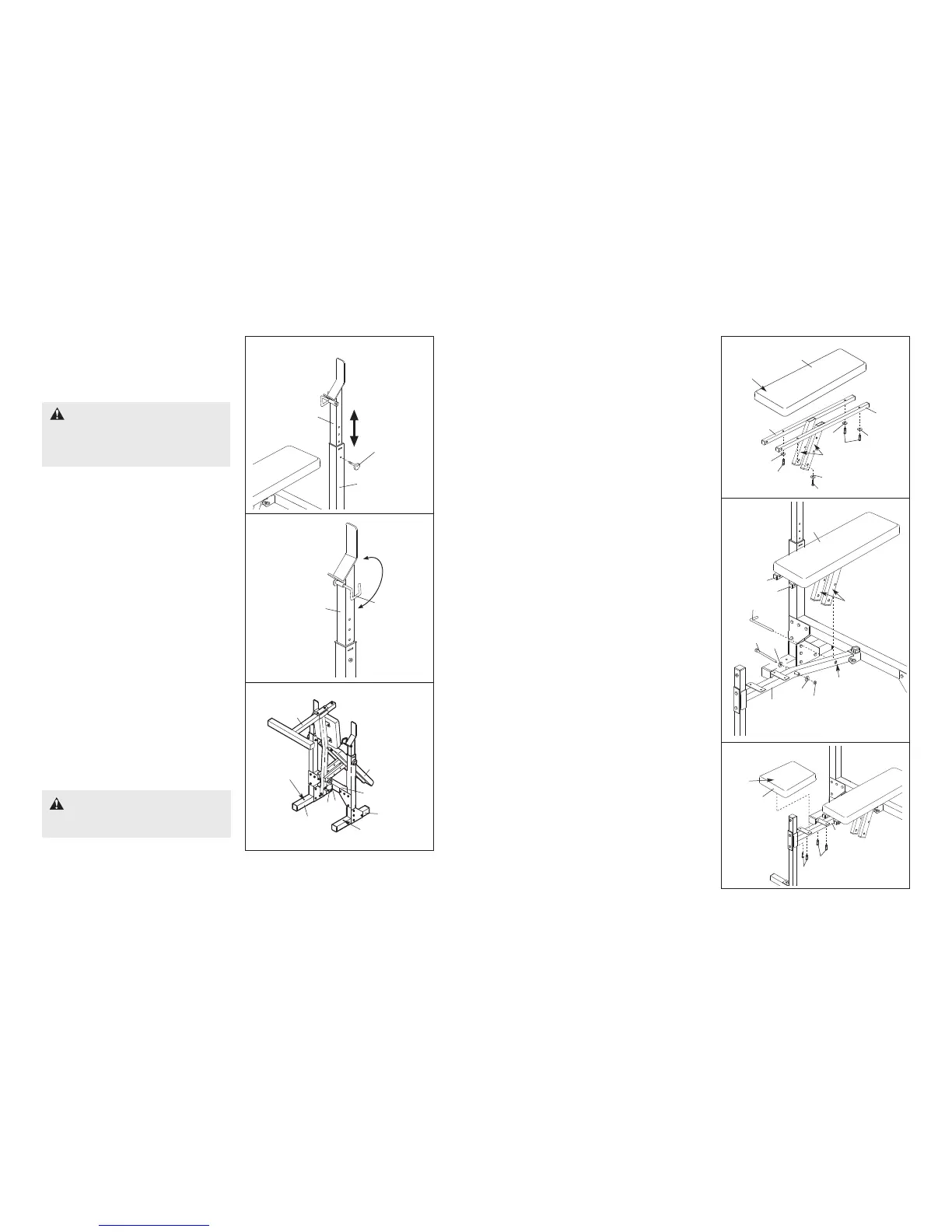
5. Identify the Right and Left Backrest Frames (5,
41) by the position of the adjustment tubes, and
o
rient them as shown.
O
rient the Backrest (6) with the wide end on the
side shown. Attach the Backrest to the Right and
Left Backrest Frames (5, 41) with four M6 x
38mm Screws (16) and four M6 Washers (25).
Do not tighten the Screws yet.
6. Lubricate the M10 x 175mm Bolt (17). Attach the
Backrest Frames (5, 41) to the Bench Frame (2)
with the Bolt, two M10 Washers (24), and an M10
Nylon Locknut (19). Do not overtighten the
Locknut; the Backrest (6) must be able to
pivot easily.
Secure the Backrest (6) to the Bench Frame (2)
by inserting the Adjustment Pin (32) through the
tube in the Bench Frame and a set of holes in the
adjustment tubes. Make sure that the
Adjustment Pin is completely inserted
through both adjustment tubes.
Tighten the four M6 x 38mm Screws (16) used
in step 5.
5
41
25
25
25
25
16
16
16
6
5
41
5
6
Wide
End
6
17
32
24
24
19
2
Tube
Adjustment
Tubes
Adjustment
Tubes
7
7.
Orient the Seat (11) with the wide end on the side
shown. Attach the Seat to the Bench Frame (2)
with four M6 x 16mm Screws (15).
2
15
15
11
Wide
End