上海维宏电子科技股份有限公司
Weihong Electronic Technology Co., Ltd.
- 114 - Specialized, Concentrated, Focused
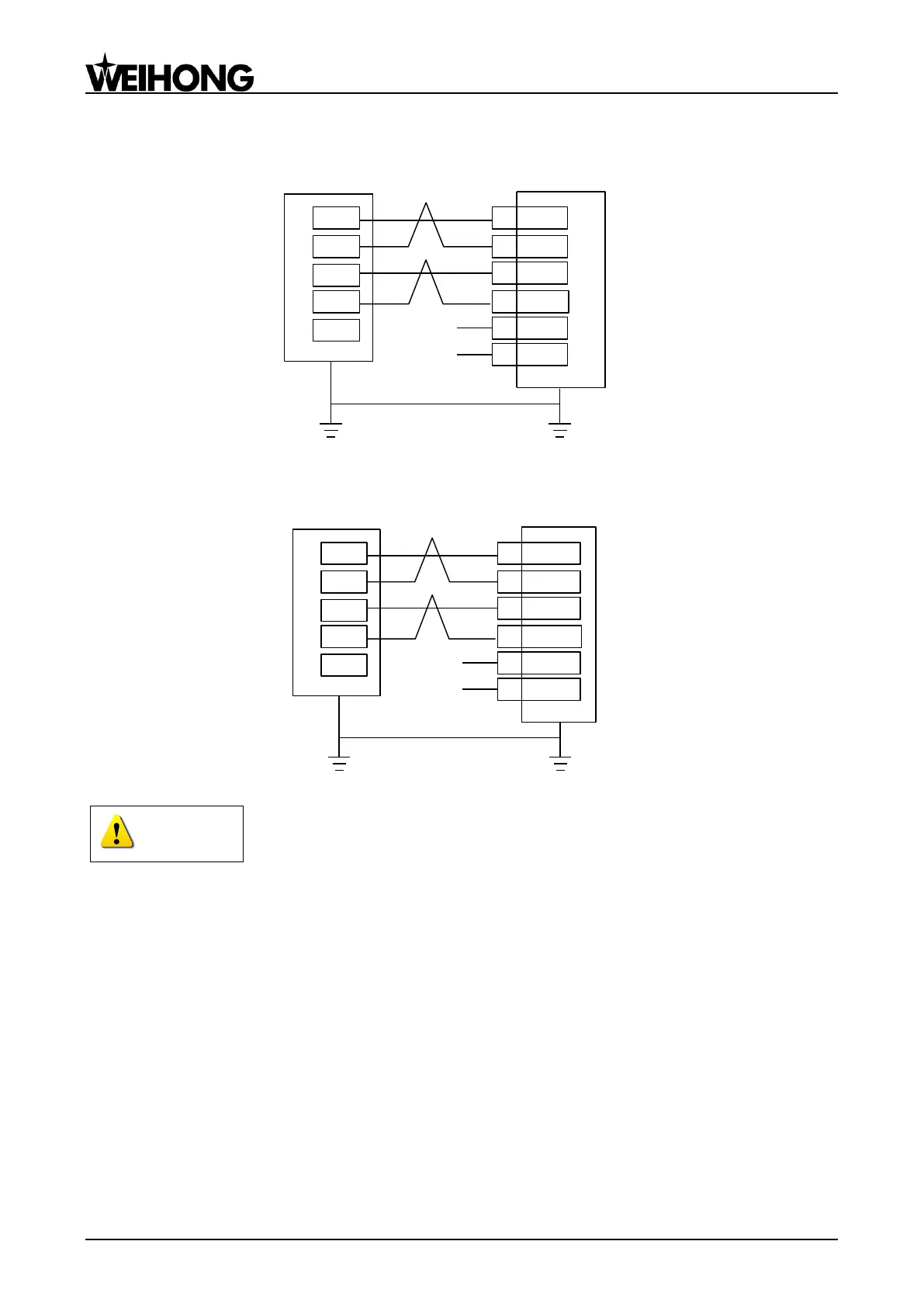
5.5.1.8 Wiring with FUJI FALDIC-β Servo Driver
21 *CB
20 CB
8 *CA
7 CA
1 P24
14 M24
24V
COM
FUJI FALDIC-ß Servo Driver
D-
+5V
P+
P-
D+
Lambda 3S/3L Series
5.5.1.9 Wiring with STONE GS Servo Driver
Z-axis Brake Line
(Black)
Z-axis Brake Line
(Red)
5 BRAKE-
28 DIR-
13 DIR+
27 PUL-
12 PUL+
21 BRAKE+
STONE GS Servo Driver
D-
+5V
P+
P-
D+
Lambda 3S/3L Series
Wirings of X axis, Y axis, and Z axis are the same. Only Z axis has two brake signal lines which can be connected
to relay to control brake.
5.5.2 Lambda 4S/5S Series
Wiring diagrams in this part are the wiring diagrams of control system-axes control-driver motion.
When users want to use one axis of the control system to control the motion of two drivers, the wiring
diagram is as shown in Figure 2 in chapter 5.5.2.2 and Figure 4 in chapter 5.5.2.6 (take YASKAWA driver
and DELTA driver as an example; for YASKAWA server, its alarm signal wiring is NC type, while for
DELTA server, its alarm signal wiring is NO type).