上海维宏电子科技股份有限公司
Weihong Electronic Technology Co., Ltd.
- 38 - Specialized, Concentrated, Focused
2.3 Driver Interface
2.3.1 Lambda 3S/3L Series Controller
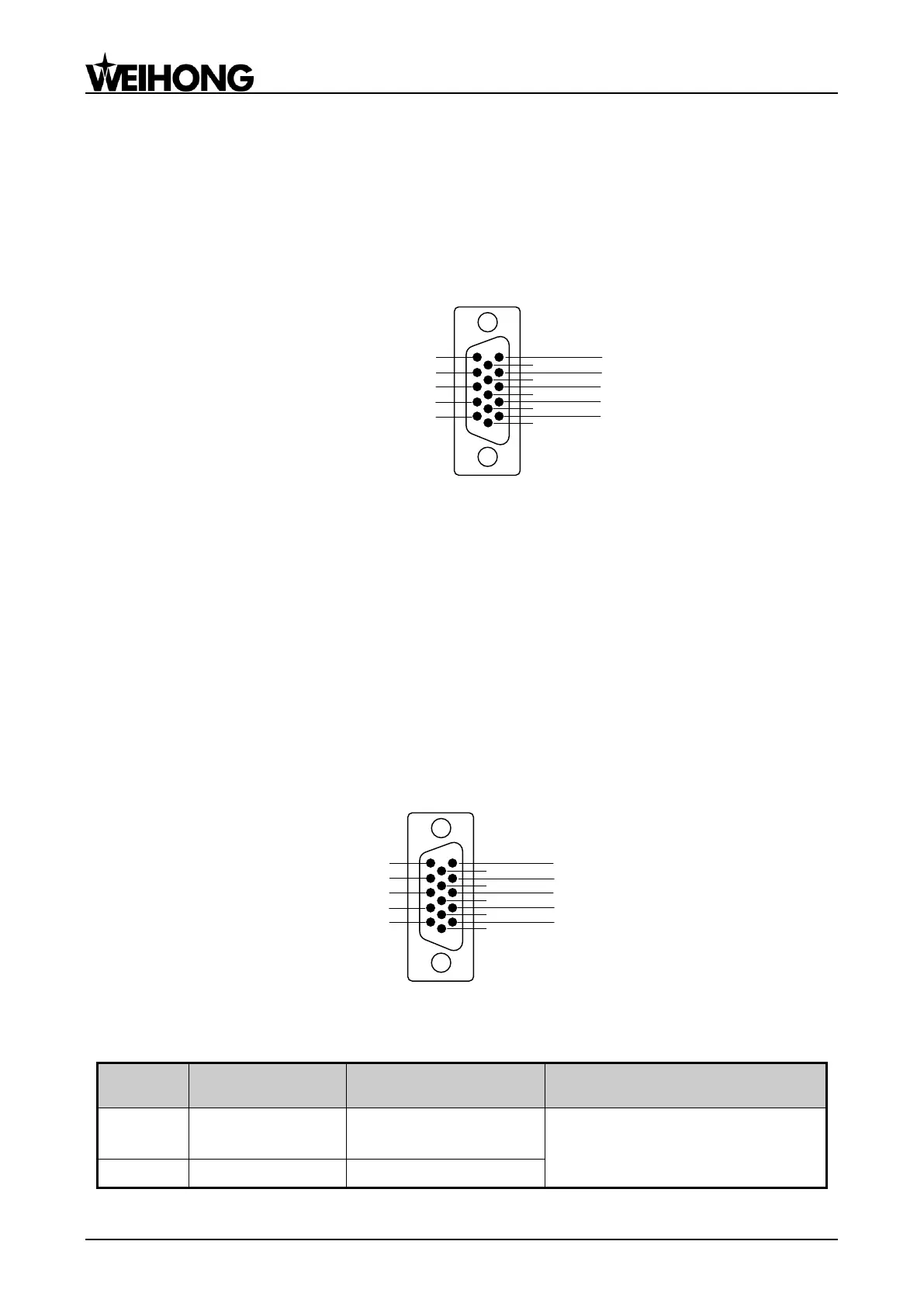
Lambda 3S/3L series controller provides 3 pulse feed driver interfaces for X/Y/Z axis. The 3
interfaces are 15-pin D-type sockets, and the pins definition is as shown in Fig. 2-29.
5
4
10
9
8
3
7
6: +5V (Blue)
2
1
15: GND (Brown)
14: D- (Green Black)
13: D+ (Green)
12: P- (Yellow Black)
11: P+ (Yellow)
Fig. 2-29 Definition of driver interface
Only 6 of the pins should be wired when connected with a stepping driver, and the 6 wires at one
end of DB15 provided by WEIHONG are distinguished by colors. You just need to connect the wires
according to the colors shown in the above picture.
+5V, GND: supplying 5VDC power to a stepping driver;
P+, P-: pulse (PULS), differential output signals;
D+, D-: direction (DIR), differential output signals.
2.3.2 Lambda 4S/5S Series Controller
Lambda 4S/5S series controller provides up to 5 pulse feed driver interfaces for X/Y/Z/the fourth/the
fifth axis. The 5 interfaces are 15-pin D-type sockets, and the pins definition is as shown in Fig. 2-30.
5: C+
4: B-
10: CLR
9: SON
8: ALM
3: B+
7: C-
6: +24V
2: A-
1: A+
15: GND
14: DIR-
13: DIR+
12: PUL-
11: PUL+
Fig. 2-30 Definition of driver interface
Servo Driver Interface Definition
Feedback signal of
encoder phase A
Input, differential signal
transmission mode
Receive the differential output from
encoder signal (phase A, B, C) of
driver frequency divider (equaling to
Input, differential signal