上海维宏电子科技股份有限公司
SHANGHAI WEIHONG ELECTRONIC TECHNOLOGY CO., LTD.
44 / 116
After the Z axis has gone to the mechanical origin, the symbol will be displayed
before Z axis in the coordinate area.
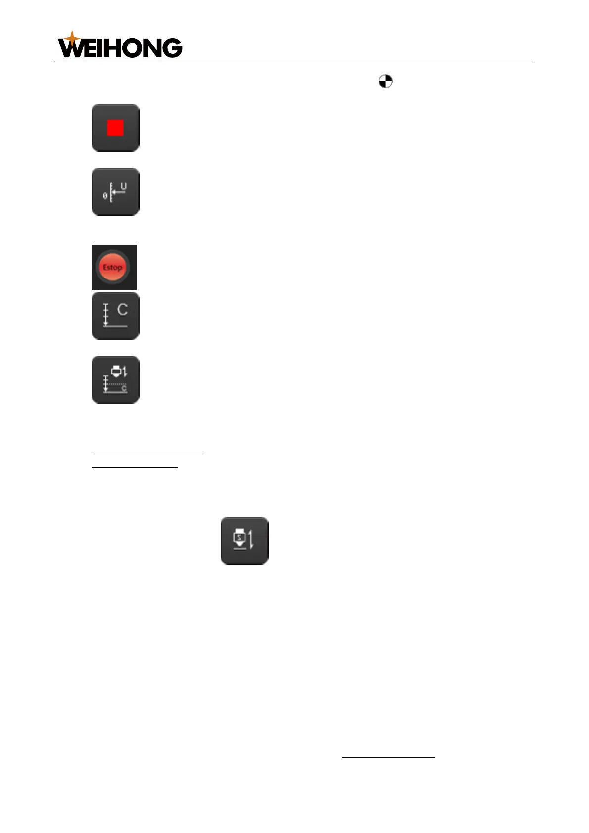
Stop: Makes the system stop current movement and enter idle state. You
can click this button to interrupt system tasks normally during follow control.
Servo Calibrate: Only available in velocity loop control mode. If it is
highlighted, the system automatically executes compensation and clears servo zero
drift.
Estop: Executes system emergency stop.
Calibrate: Highlight the button to calibrate the cutter. Deselect the button
to stop automatic calibration.
One Key Calibrate: Makes the system execute one-key cutter calibration.
4.1.5 Follow Control Area/Follow Parameter Setting Area
Includes
Main Parameter Area
Data Chart Area
4.1.5.1 Main Parameter Area
Click the System tab to access this area. The following parameters are displayed:
Real-time monitor parameters (cannot be modified on this page):
o Enable: After the Follow button is highlighted, the status of this
parameter will become Enabled.
o Z Speed: Shows the current Z-axis movement speed.
o Z Position: Shows the current Z-axis mechanical coordinates.
o Capacitance: Shows the current capacitance value. The closer the cutter
from the material, the smaller it is. When the cutter touches the material
(metal), it becomes 0.
Some of the common follow parameters (can be modified on this page):
o Follow Height: The height of the cutter during following.
o Max Speed: The cutter maximum speed during following.
o Follow Gain: Controls the follow sensitivity.
o Z Up Pos.: Specifies the coordinate you want the Z axis to be after it goes to
the mechanical origin and the following or machining is stopped.
To modify the parameters, click the parameter current value and enter the new
value. For details about follow parameters, see Follow Parameter.