13
ASSEMBLY AND ADJUSTMENTS
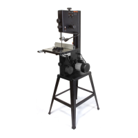
ADJUSTING THE BEVEL ANGLE INDICATOR
If the blade is at a 90° angle and the bevel indicator (A, Fig 20) does not
indicate 0° on the scale, an adjustment can be made:
1. Place a combination square (A, Fig.19) on the table and up against
the flat portion of the blade (B, Fig.19).
2. Unlock the bevel locking lever (A, Fig 18) by pulling the lever all the
way to the right. Push in and then turn the exterior handwheel (B, Fig
18) until the blade is set at a perfect 90°. Lock the bevel locking lever.
3. Loosen the screw (A) Fig.20 which secures the bevel indicator (B).
Readjust the position of the bevel indicator so it aligns with the 0° on the
bevel scale. Retighten screw (A).
ADJUSTING THE BLADE PARALLEL WITH THE TABLE T-
SLOT (FIG 22)
The blade must be aligned parallel with the table T-slot. Using a combi-
nation square (A), measure the distance from the back edge of the blade
(C) to the table T-slot (B). Pivot blade forward 180° and remeasure the
distance using the exact same point on the blade. The difference be-
tween both measurements must be equal to or less than 1/64”.
If an adjustment is necessary, loosen the four cap screws (D) that fix the
blade and motor assembly to the table top. Make the needed adjustment
to the blade position until both measurements are equal or less than
1/64” and retighten the four cap screws (D).
MARKABLE INSERT ON TABLE
A plastic markable insert (A, Fig 21) located in front of the saw blade is
provided for marking the location of the saw blade kerf (cut width) on
the workpiece.
1. Place the miter gauge in the left T-slot and make sure the blade angle
is exactly 90°.
2. Place and firmly hold a workpiece against the miter gauge body and
make the cross cut.
3. Turn the saw off. Once the blade has come to a complete stop, pull
the miter gauge back until the freshly cut workpiece is over the markable
insert (A, Fig. 21).
4. Using a sharp pencil, mark a line on the insert at the edge of the
freshly cut workpiece. Repeat steps 1-4 but place the miter gauge in the
right T-slot instead to make the second mark on the insert.
Note: Both these lines indicate the blade kerf made by the blade. If you
change the blade the marks will need to be erased and the above steps
will need to be repeated.
Fig. 16
Fig. 17
Fig. 18
Fig. 19
Fig. 20
Fig. 21
Fig. 22