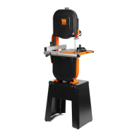
TILTING THE TABLE
1. Unlock the two table lock knobs (Fig. 18 - 1). Use the bevel scale
indicator (Fig. 18 - 2) to adjust the table to the correct angle. The table
can be beveled to the right 45° and to the left 15°.
2. If tilting the table to the left, the positive stop bolt will need to be
lowered. Follow the directions below to reset the positive stop bolt.
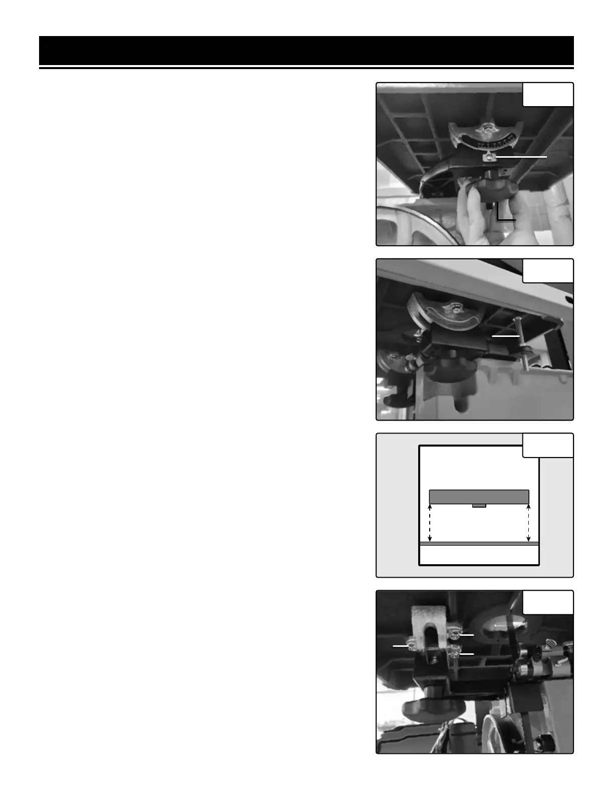
To set the positive stop bolt:
1. Make sure that the tool is OFF and disconnected from the power
source.
2. Make sure that the blade is properly tensioned. Refer to the " SAW
BLADE TENSION & TRACKING" section.
3. Unlock the two table lock knobs and loosen the hex nut on the posi-
tive stop bolt.
4. Raise the blade guard by unlocking the guide post lock knob (Fig.
17 - 1).
5. Place a machinist's square (not included) flat on the table against
the blade. Raise or lower the positive stop bolt (Fig. 19 - 1) until the
table is level and square with the blade. Retighten the hex nut on the
positive stop bolt.
6. Rest the table on the positive stop bolt and retighten the table lock
knobs. Check that the bevel scale indicator is pointing to "0" on the
bevel scale. If not, loosen the bevel scale indicator screw (Fig. 18 - 2)
and reposition it to point to "0". Retighten the screw.
ALIGNING THE TABLE
When first installing the table, it is important to make sure that the
blade is parallel to the miter gauge slot on the table.
1. Make sure that the tool is OFF and disconnected from the power
source.
2. Make sure that the blade is properly tensioned. Refer to the " SAW
BLADE TENSION & TRACKING" section.
3. Place a straight edge along the blade. The straight edge should be
lightly touching the front and back of the blade (Fig. 20).
4. Measure from both ends of the straight edge to the miter gauge
slot. If the measurements are the same, the blade and table are paral-
lel and no further adjustments are needed. If the measurements are
not the same, continue on to step 5.
5. Loosen the six flange bolts (Fig. 21 - 1) (3 of 6 shown) that secure
the table to the trunnion brackets.
6. Adjust the table until both measurements are equal.
7. Retighten the six flange bolts.
ASSEMBLY & ADJUSTMENTS
Fig. 18
1
2
Fig. 19
1
Fig. 21
1
1
1
Fig. 20
Top
View
Table
Blade
Miter Gauge Slot
Straight Edge
17
 Loading...