14
ASSEMBLY & ADJUSTMENTS
WARNING! If the tension in the blade is too high, it runs the risk of breaking. If the tension is too low, there
is a risk of the blade slipping and stopping during a cut.
ADJUSTING BLADE TENSION
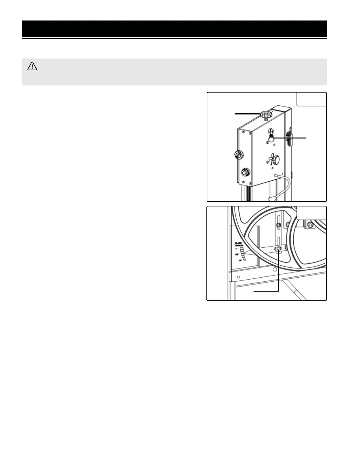
1. Raise the upper blade guide fully using the saw blade tension
knob located on the top of the machine (Fig. 15 - 1). Take the blade
width into consideration during the adjustment.
2. Check the tension by pushing with a finger against the side
of the blade halfway between the table and the upper guide. The
blade should not flex more than 2 mm.
3. Check the adjustment using the blade tension indicator on the
inside of the upper housing. The scale indicates the correct adjust-
ment for a certain width of blade. The indicator should be pointing
towards the width of blade being used.
4. Turning the setting knob clockwise increases the blade tension
while turning the setting knob counterclockwise decreases ten-
sion.
5. After achieving the desired tension, the tension release lever can
be used to easily loosen and tighten the spindles without changing
the amount of tension (Fig. 15 - 2).
ADJUSTING THE BLADE TENSION INDICATOR
The blade tension indicator can be adjusted for blades known to
be cut over or under length by different manufacturers. With mod-
erate tension on the blade, loosen the set screw (Fig. 16 - 1) and
adjust the blade indicator up or down as needed. Retighten the set
screw.
UPPER BLADE GUIDE ADJUSTMENT
Fig. 15
1
2
The height of the upper blade guard should be adjusted prior to every operation to accommodate the height of
the workpiece (the blade guard should be no more than one-fifth of an inch (3mm) from the upper edge of the
workpiece).
1. Use the adjustment knob (Fig. 17 - 1) to adjust the height of the upper blade guide. Use the outer locking knob
to secure the guard in place when it has reached the desired height.
2. Loosen the knobs on the side of the blade guard (Fig. 17 - 2 and 17 - 3) and adjust both the thrust and guide
bearings so that they are positioned approximately 1/10 of one inch (2mm) or less (0.5mm for the guide bearing)
away from the blade. The inside knob (Fig. 17 - 3) adjusts the thrust bearing, holding the back of the blade in place.
The outside knob (Fig. 17 - 2) adjusts the guide bearings, moving the blade left and right.
3. Once desired adjustments have been achieved (when the bearings are all roughly 0.1 to 0.5 mm away from the
blade) (Fig. 18, Fig. 19), tighten the knobs to secure the bearing guides in place.
Fig. 16
1
 Loading...