ASSEMBLY & ADJUSTMENTS
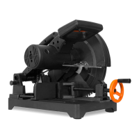
GUARD OPERATION
NOTE: Keep hands clear of the blade when the operating handle
is lowered (Fig. 2 - 1). Do not interfere with the proper move-
ment of the blade guard (Fig. 2 - 2).
When the handle is lowered, the blade guard raises automati-
cally. When the handle is raised, the blade guard returns to its
safety position, covering the blade.
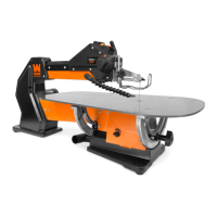
PLUNGE LOCK
To unlock the saw from the plunged position, unhook the chain
(Fig. 3 - 1) from the plunge rod on the left side of the saw arm.
To lock the saw in the plunged position, hook the chain on the
plunge rod in the tightest position possible to ensure the arm is
secured.
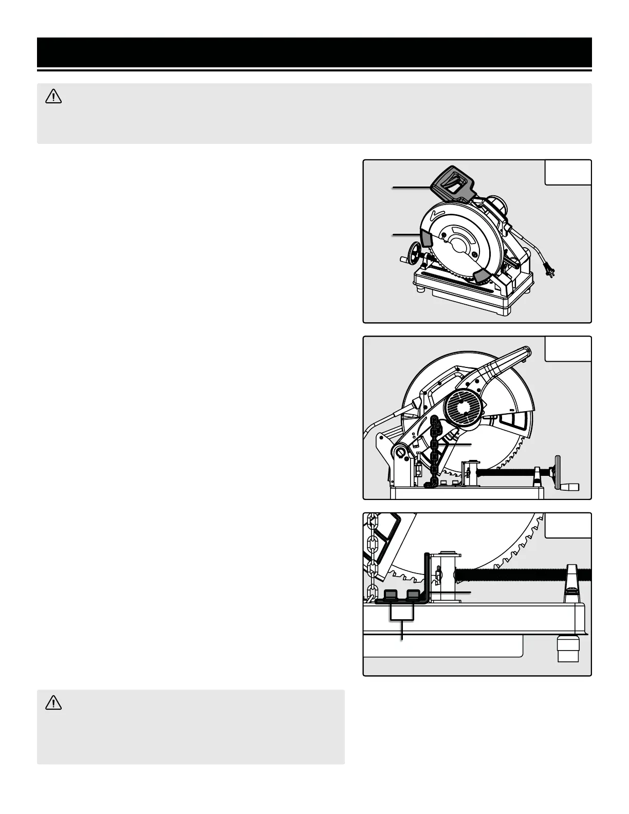
ADJUSTING THE CUTTING ANGLE
The rear vise fence can be adjusted to allow for cutting larger
work pieces or cutting at varied angles (between 0° and 45°).
To change the angle of the fence:
1. Loosen the two M10 bolts (Fig. 4 - 1) securing the fence to
the base.
2. Turn the fence (Fig. 4 - 2) to the desired angle.
3. Tighten the two M10 bolts to lock the fence into place.
To reposition the fence:
1. Loosen and remove the two M10 bolts (Fig. 4 - 1) securing
the fence (Fig. 4 - 2) to the base along with the washers on those
bolts.
2. Move the fence (Fig. 4 - 2) to the new desired location. There
are two different locations that the fence can be fastened in,
choose the position that is best for your work piece size.
3. Replace the two M10 bolts (Fig. 4 - 1) along with their wash-
ers, making sure that the washers are in the same order as origi-
nally assembled.
Fig. 2
1
Fig. 3
Fig. 4
1
2
2
WARNING! Do not plug in or turn on the tool until it is fully assembled according to the instructions. Read
through and become familiarized with the following procedures of handling and adjusting your chop saw. Failure
to follow the safety instructions may result in serious personal injury.
WARNING! Be sure the fence is securely in place before
making any cuts with the saw. Failure to do so can cause the
fence to move during the cut, which could result in serious
personal injury.
2
1
11

 Loading...