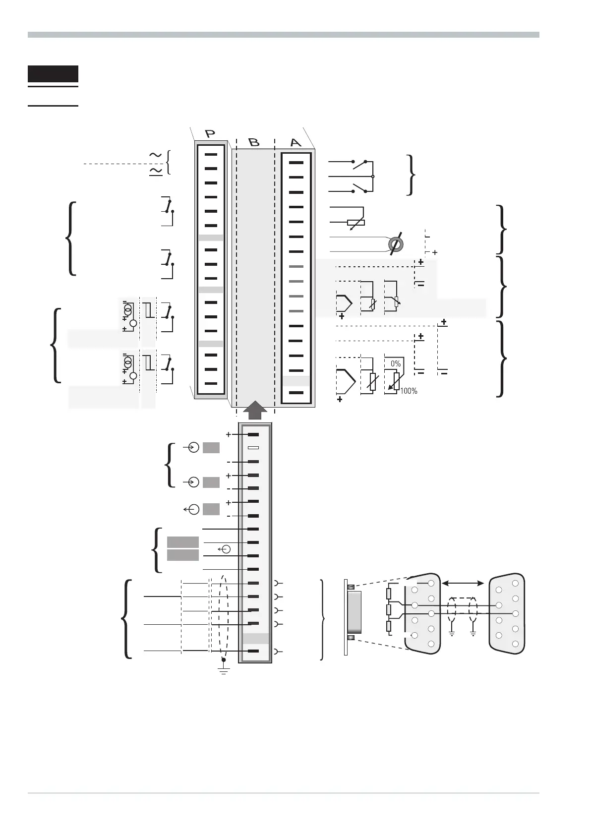
2 Electrical connections
2.1 Connecting diagram
g
Dependent of order, the controller is fitted with :
w
flat-pin terminals 1 x 6,3mm or 2 x 2,8mm to DIN 46 244 or
w
screw terminals for 0,5 to 2,5mm²
Electrical connections
Connecting diagram 6 8800 process controller
1
3
4
5
6
7
8
9
10
11
12
13
14
15
17
(2)
(16)
mA
(mV)
(mV)
Volt
mA
INP2
INP3
INP1
di2
di1
1
2
3
4
5
6
7
8
9
10
11
12
13
14
15
Option
1
2
3
4
5
6
7
8
9
10
11
12
13
14
15
17
(16)
OUT1
OUT2
OUT3
OUT4
90...250V
24 V UC
0%
100%
V
V
mA
HC
di2
di3
U
T
RXD-B
GND
RXD-A
TXD-B
TXD-A
RS485 RS422
Modbus RTU
RGND
DATA B
DATA A
9
0
8
2
1
7
6
5
4
a
b
cd
e
f
g
a
b
c
d
e
+24V DC
24V GND
OUT5
OUT6
!
VP (5V)
DGND
RxD/TxD-N
RxD/TxD-P
PROFIBUS-DP
Schirm/
Screen
5
9
4
8
3
7
2
6
1
5
9
4
8
3
7
2
6
1
390 [
390 [
220 [
DGND
VP (5V)
max.
1200m
Adapter
Profibus DP