5.3 Input scaling
When using current, voltage or resistance signals as input variables for InP.1,
InP.2 or/and InP.3 scaling of input and display values at parameter setting level
is required. Specification of the input value for lower and higher scaling point is
in the relevant electrical unit (mA/V/Ω).
5.3.1 Input Inp.1 and InP.3
g
Parameters InL.x,OuL.x, InH.x and OuH.x are only visible if
ConF / InP.x/Corr = 3 is chosen.
In addition to these settings, InL.x and InH.x can be adjusted in the range
(0...20mA / 0...10V / Ω) determined by selection of S.tYP .
a
For using the predetermined scaling with thermocouple and resistance
thermometer (Pt100), the settings for InL.x and OuL.x and for InH.x and
OuH.x must have the same value.
g
Input scaling changes at calibration level (r page 65) are displayed by input
scaling at parameter setting level. After calibration reset (OFF), the scaling
parameters are reset to default.
5.3.2 Input InP.2
In addition to these settings, InL.2 and InH.2 can be adjusted in the range
(0...20/ 50mA/Ω) determined by selection of S.tYP.
Parameter setting level
Input scaling 64 8800 process controller
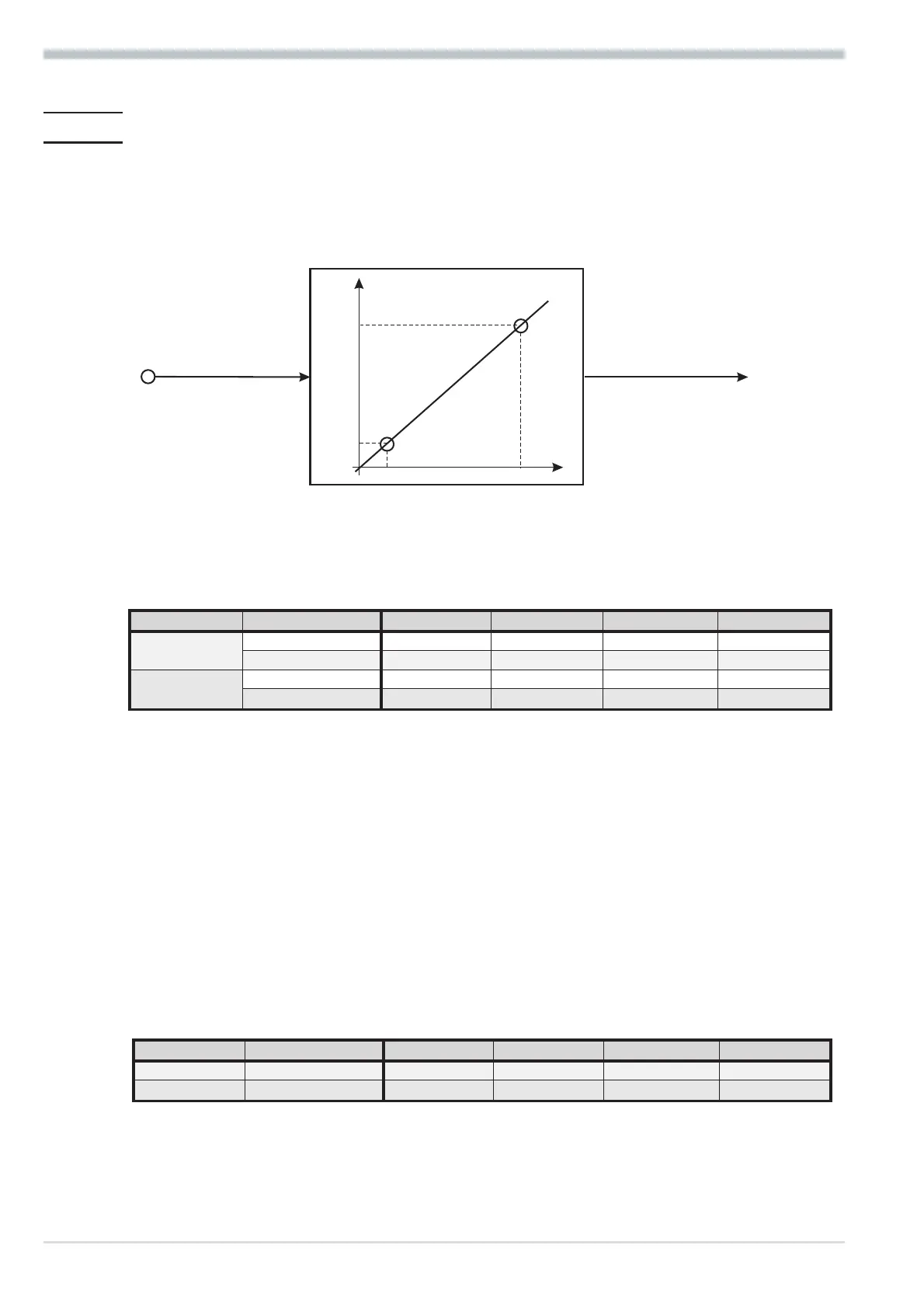
mA/V
phys.
quantity
mA / V
phys. quantity
OuH.x
OuL.x
InH.x
InL.x
S.tYP Input signal InL.x OuL.x InH.x OuH.x
30
(0...20mA)
0 … 20 mA 0 any 20 any
4 … 20 mA 4 any 20 any
40
(0...10V)
0 … 10 V 0 any 10 any
2 … 10 V 2 any 10 any
S.tYP Input signal InL.2 OuL.2 InH.2 OuH.2
30 0 … 20 mA 0 any 20 any
31 0 … 50 mA 0 any 50 any