must
always
be
above
the water line at
all
angles
of
vessel
operation to
prevent
siphoning.
The
vent,
when
used,
must
have
its vent
hose
or tube
routed
so
as
to
be
above
the water
line
and
to
remain
empty of water
when
the
engine
is
shut down to allow air to enter through this vent
and
prevent
siphoning.
Exhaust Back-Pressure
The
exhaust
discharge
hose
must
be
of
adequate
size
and
minimal
run
to prevent
excessive
exhaust
back-pressure.
Exhaust
baCk-pressure
should
be
checked
before
to a
gen-
erator
is
put into
service.
(Refer
to the illustration.) exces-
sive
back-pressure will affect the engine's performance
and
the generator's power output.
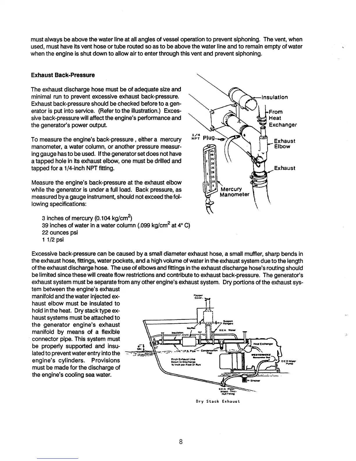
To
measure
the engine's back-pressure, either a mercury
manometer,
a water
column,
or another
pressure
measur-
ing
gauge
has
to be
used.
If the generator
set
does not
have
a tapped
hole
in
its
exhaust
elbow,
one
must
be
drilled
and
tapped for a 1/4-inch
NPT
fitting.
Measure
the engine's back-pressure at the
exhaust
elbow
while
the generator
is
under a
full
load.
Back
pressure,
as
measured
by a
gauge
instrument,
should
not
exceed
the fol-
lowing
speCifications:
3
inches
of mercury
(0.104
kg/cm
2
)
39
inches
of water
in
a water column
(.099
kg/cm
2
at
4
0
C)
22
ounces
psi
11/2
psi
Exhaust
Elbow
Exhaust
Excessive
back-pressure
can
be
caused
by a
small
diameter
exhaust
hose,
a
small
muffler,
sharp
bends
in
the
exhaust
hose,
fittings, water pockets,
and
a
high
volume of water
in
the
exhaust
system
due
to the length
of the
exhaust
discharge
hose.
The
use
of
elbows
and
fittings
in
the
exhaust
discharge hose's routing
should
be
limited since
these
will
create
flow restrictions
and
contribute to
exhaust
back-pressure.
The
generator's
exhaust
system
must
be
separate
from
any
other engine's
exhaust
system.
Dry portions of the
exhaust
sys-
tem
between
the engine's
exhaust
manifold
and
the water injected
ex-
haust
elbow
must
be
insulated
to
hold
in
the
heat.
Dry
stack type
ex-
haust
systems
must
be
attached to
the generator engine's exhaust
manifold by
means
of a flexible
connector
pipe.
This
system
must
be
properly supported
and
insu-
lated
to prevent water entry into the
engine's
cylinders. Provisions
must
be
made
for the discharge of
the engine's
cooling
sea
water.
r
loin
8
'
......
'
c--!M
II
Dry
Stack
Exhaust