IWARNINGI
When
installing the optional remote start
panel
or the optional remote instrument
panel,
it
is
the installer's responsibility to comply with
U.S.
Coast
Guard
Standards
33
CFR
PART
183.
Generator AC Load Connections
CAUTION
ALL
115
VOLT
LOADS
MUST
BE
DIVIDED
UP
AND
CONNECTED
IN
SUCH
A
MANNER
THAT
CURRENT
FLOWING
IN
ANY
OF
THE
THREE
LEGS
(G1,
G4,
G2/G3)
DOES
NOT
EXCEED
THE
LOWEST
AMPERAGE
RATING
ON
THE
GENERATOR'S
DATA
PLATE.
The
generator
data
plate
gives
the
voltage,
amperage
and
hertz
rating
of
the
generator.
The
generator
set
wir
ing
decal
located
on
the
cover
of
the
generator
mounted
control
panel
shows
the
electrical
connections
for
115
or
230
volt
AC
output~
This
is
a
single
phase,
4
lead
wi
th
vol
tage
com-
binations
of
115
volt,
two
wire,
or
115/230
volt,
three
wire.
All
115
volt
devices
must
be
connected
to
one
of
the
two
115
volt
sources
and
all
230
volt
devices
must
be
connected
to
the
230
volt
source.
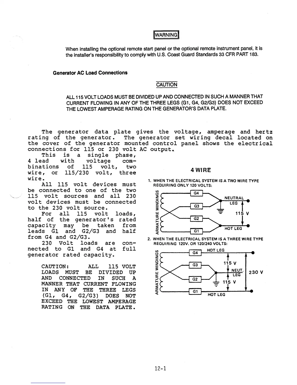
For
all
115
volt
loads,
half
of
the
generator's
rated
capacity
may
be
taken
from
leads
Gl
and
G2/G3
and
half
from
G4
and
G2/G3.
230
Volt
loads
are
con-
nected
to
Gl
and
G4
at
full
generator
rated
capacity.
CAUTION:
ALL
115
VOLT
LOADS
MUST
BE
DIVIDED
UP
AND
CONNECTED
IN
SUCH
A
MANNER
THAT
CURRENT
FLOWING
IN
ANY
OF
THE
THREE
LEGS
(GI,
G4,
G2/G3)
DOES
NOT
EXCEED
THE
LOWEST
AMPERAGE
RATING
ON
THE
DATA
PLATE.
4WIRE
1.
WHEN THE ELECTRICAL SYSTEM
IS
A
TWO
WIRE TYPE
REQUIRING
ONLY
120 VOLTS:
~'-----1
z
w
a:
:)
....
<t
::E
~'------I
2. WHEN THE ELECTRICAL SYSTEM
IS
A THREE WIRE TYPE
REQUIRING 120V.
OR
120/240 VOLTS:
~'-----i
z
o
z
~
w
a:
:)
I-
<t
::E
~'------;
12-1
NEUT.
230
V
LEG
 Loading...