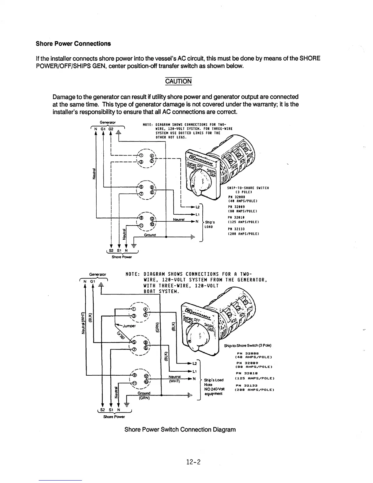
Shore Power Connections
If the installer connects shore power into the vessel's
AC
circuit, this must
be
done by means of the
SHORE
POWER/OFF/SHIPS
GEN,
center position-off transfer switch
as
shown below.
CAUTION
Damage to the generator can result if utility shore power and generator output are connected
at the
same
time. This type of generator damage is not covered under the warranty; it
is
the
installer's responsibility to ensure that
all
AC
connections are correct.
Generator
NOTE:
DIAGRAM
SHOWS
CONNECTIONS
FOR
TWO-
~
WIRE.
128-VDLT
SYSTEM.
FOR
THREE-WIRE
i
:z
GeneralOr
N
GI'
)
-
t
=L..
______
SY_S-,TEM
USE
DOITED
LINES
FOR
THE
OTHER
HOT
LEGS.
I
I
/,.--
....
L
____
-(-<J) ~\
~-
r-----\Q)
/
I ,
__
...
I
I
I
I
----,
I
I
I
I
I
I
I
I
I
L_L2
Ship'S
LOAD
SHIP-TO-SHORE
SWITCH
(3
POLEI
PN
328B8
(48
AMPS/POLE)
PN
32B89
(8B
RMPS/POLE)
PH
32818
(125
AMPS/POLE)
PN
32133
(288 AMPS/POLE)
NOTE:
DIAGRAM
SHOWS
CONNECTIONS
FOR
A
TWO-
WIRE.
120-VOLT
SYSTEM
FROM
THE
GENERATOR.
WITH
THREE-WIRE.
120-VOLT
I--
_____
..::B..::.O"-AT~S
YSTEM.
/"--
......
,
~-~Dl
4'·
);,
....
,-+---,
,
"
I
" /
-_
....
..--
....
/
'\
l2
L---.L1
Ship·to-Shore
Switch
(3
POle)
PH
328BB
(411
AMPS/POLE)
PH
3211119
L---+--Ir---+W
\
Neutral
ir-~;-~ro==:::'n~/;"';~:~~:~~:f'N:H:T:)
~~.,:
(BB
AMPS/POLE)
PN
32919
(125
AMPS/POLE)
:Z~
t (GRN)
~
Shore
Power
Ship's
Load
Note
NO
240-V0It
equipment
PH
32133
(21111
AMPS/POLE)
Shore Power Switch Connection Diagram
12-2