BATTERY
CHARGING
CIRCUIT
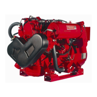
The DC Circuit on the
BCG
functions to start, operate and
stop the generator's engine. The circuit is best understood
by
reviewing the DC Wiring Diagram and Wrring Schematic.
Tue engine's DC wiring is designed with three simple basic
circuits: start, run and stop.
The engine has a 12 volt DC electrical control
circuit that is
shown on the
Wrring Diagrams. Refer to these diagrams
when troubleshooting or when servicing the DC electrical
system or the engine.
BATTERIES
A
CAUTION:
To
avoid
damage
to
the
battery
charg-
ing
circut,
never
shut
off
the
engine
battery
switch
while
the
engine
is
running.
Shut
off
the
engine
battery
switch,
however,
to
avoid
electrical
shorts
when
work·
ing
on
the
engine's
electrical
circuit.
Specificatfons
The minimum recommended capacity .of the battery used in
the engine's 12-volt
DC
control circuit is
400
CCA.
BATTERY
CHARGER
Battery
Maintenance
Review the manufacturer's recommendations and then estab-
lish a systematic maintenance schedule for your engine's
starting batteries and house batteries.
• Monitor your voltmeter for proper charging during engine
operation.
• Check the electrolyte level and specific gravity with a
hydrometer.
• Use only distilled water to bring electrolytes to a proper
level.
•
Make certain that battery cable connections are clean and
tight
to
the battery posts (and to your engine).
• Keep your batteries clean and free
of
corrosion.
A
WARNING:
Sulfuric
acid
in
lead
batteries
can
cause
severe
bums
on
skin
and
damage
clothing.
Wear
protective
gear.
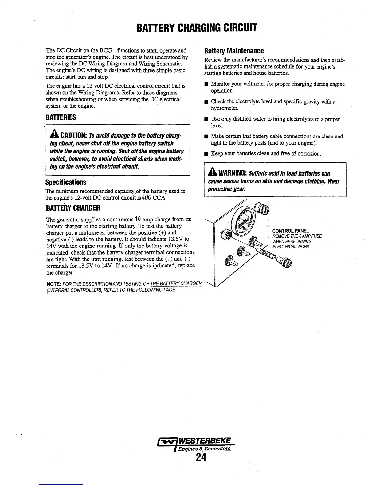
The generator supplies a continuous 10 amp charge from its
"-
battery charger
to
the starting battery.
To
test the battery
charger put a multimeter between the positive ( +) and
negative (-) leads to the battery. It should indicate
13.SV
.to
14V with the engine running.
If
only .the battery voltage is
indicated, check
that
the battery charger terminal connections
are tight. With the unit running, test between the (
+) and (-)
terminals
f0r..B.5V to
14V.
If
no charge is igdicated, replace
the charger.
NOTE:
FOR
THE
DESCRIPTION
AND
TESTING
OF
THE
BATTERY
CHARGEN
(INTEGRAL
CONTROLLER),
REFER
TO
THE
FOLLOWING
PAGE.
Engines &
GeneratoL~
24