OPERATION
17
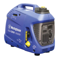
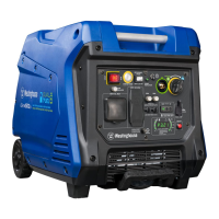
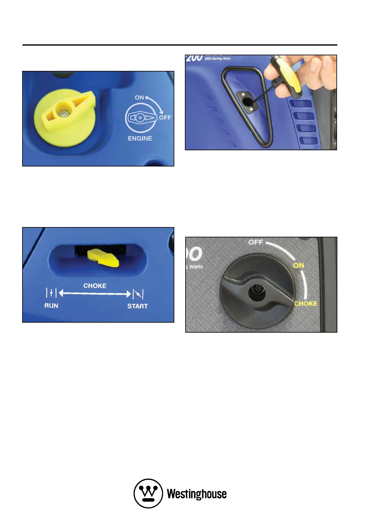
2. Turn the engine and fuel control switch anti-
clockwise to the ON position (see Figure 14).
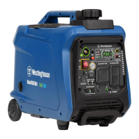
3. Move the choke lever rightwards to the START
position if starting a cold engine (see Figure 15).
To re-start a warm engine, leave the choke lever
pushed left to the RUN position.
4. Whilst holding the generator down with one
hand, firmly grasp the recoil starter handle with
your other hand and pull it slowly until you feel
increased resistance. At this point, pull it briskly
up and away from the generator (see Figure 16).
Do not allow the starter handle to snap back
against the engine, but instead return it gently to
prevent starter damage. Do not allow the starter
cord to rub against other parts of the generator.
5. As the engine starts running and warms up,
gradually move the choke lever leftwards to the
RUN position.
6. Connect electrical cords or devices into the 240-
Volt AC, 12-Volt DC accessory or 5-Volt DC USB
outlets, as required.
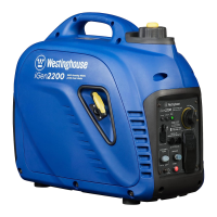
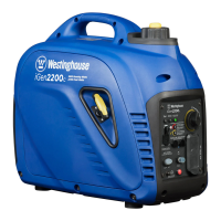
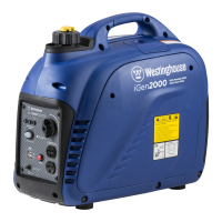
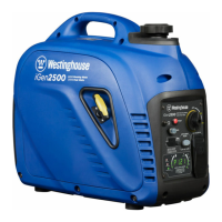
iGen2200 & 2500 Starting
1. Turn the fuel cap vent to the ON position
(see Figure 13).
2. Turn the engine, fuel and choke control switch
clockwise to the CHOKE position if starting a
cold engine (see Figure 17). To re-start a warm
engine, turn the knob to the ON position.
3 Whilst holding the generator down with one
hand, firmly grasp the recoil starter handle with
your other hand and pull it slowly until you feel
increased resistance. At this point, pull it briskly
up and away from the generator (see Figure 16).
Do not allow the starter handle to snap back
against the engine, but instead return it gently to
prevent starter damage. Do not allow the starter
cord to rub against other parts of the generator.
4. As the engine starts running and warms up, turn
the engine, fuel and choke control switch anti-
clockwise to the ON position.
5. Connect electrical cords or devices into the
240-Volt AC, 12-Volt DC accessory or 5-Volt DC
USB outlets, as required.
Figure 14 – Engine and Fuel Control Switch in the
ON Position
Figure 15 – Choke Lever in the START Position
Figure 16 – Recoil Starter Handle Operation
Figure 17 – Engine, Fuel and Choke Control
Switch in the CHOKE Position
 Loading...