PAGE 17
FOR SERVICE TECHNICIAN’S USE ONLY
DO NOT REMOVE OR DESTROY
NOTE: On the gas dryer, the inlet thermistor
is located at the drum inlet vent. Refer to strip
circuit on page 24 to diagnose heater system.
Dryer does not heat:
Locate the components using figures 10a
and 10b. To access heater system components,
remove the console, top panel, and front panel.
ELECTRIC DRYER ONLY:
3Quick Check: Perform steps under “Service
Test Mode”, page 6, to test for L1 and L2
line voltage.
• If L1 is present, the thermal cutoff is
functional.
• If L2 is present, the centrifugal switch, high
limit thermostat, and the side of the heater
connected to heater relay 1 are functional.
1. Unplug dryer or disconnect power.
2. Slide the top back, remove the front panel,
front bulkhead, and drum to access thermal
components.
3. Check Heaters—on the ACU, use an
ohmmeter to measure the resistance between
the violet wire terminal on heater relay #1
and the violet wire terminal on heater relay #2.
If the resistance is ≤ 50 Ω, go to step 5.
If an open circuit is detected, go to step 4.
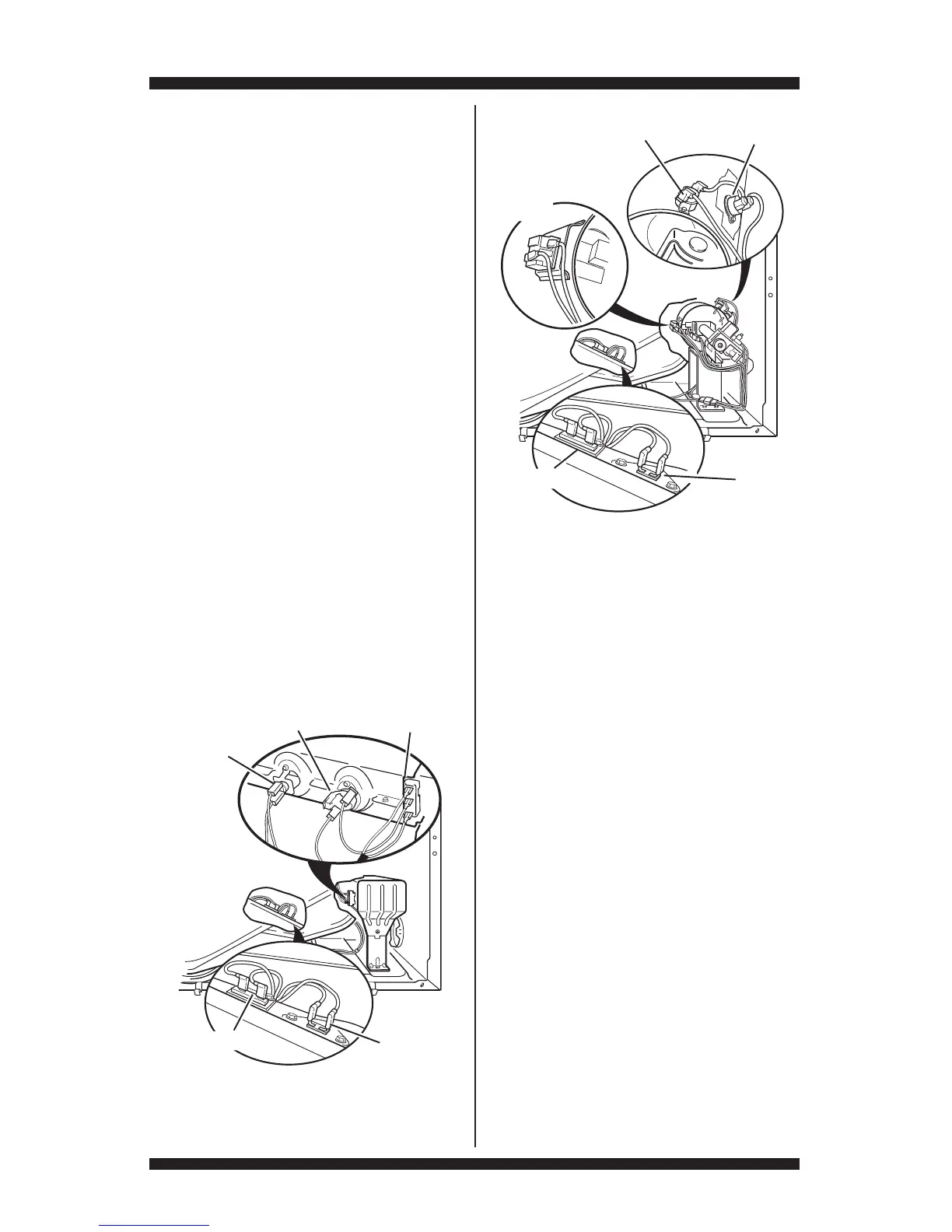
Figure 10b - Thermal components,
gas dryer, viewed from front.
Outlet
Thermistor
Thermal Fuse
Gas Dryer
Thermal
Cut-Off
High Limit Thermostat
Flame
Sensor
4. Visually check the wire connections between
each relay and their respective heaters. If the
connections look good, check for continuity
across each heater (violet wire to center red
wire). Refer to strip circuit on page 24.
Replace the heater if it is electrically open.
5. Check Thermal Cut-off—on the ACU, use
an ohmmeter to measure continuity between
P9-2 (L1) and the black wire terminal on heater
relay #1. Then, measure continuity between P9-2
(L1) and the black terminal on heater relay #2.
If there is continuity, go to step 7.
If an open circuit is detected, go to step 6.
6. Visually check the wire connections
between each relay (black wire) and the
thermal cut-off. If the connections look good,
check for continuity across the thermal cut-off.
Replace the thermal cut-off if it is
electrically open.
7. Check High Limit Thermostat—visually
check the wire connections from the heaters
and centrifugal switch to the high limit
thermostat. If the connections look good, check
for continuity across the high limit thermostat.
Replace the high limit thermostat if it is
electrically open.
Figure 10a - Thermal components,
electric dryer, viewed from front.
Inlet Thermistor/High Limit
Thermostat Assembly
Heater
Element
Electric Dryer
Thermal Fuse
Outlet
Thermistor
Thermal
Cut-Off